Sign In
Upload
Download
Table of Contents
Contents
Add to my manuals
Delete from my manuals
Share
URL of this page:
HTML Link:
Bookmark this page
Add
Manual will be automatically added to "My Manuals"
Print this page
×
Bookmark added
×
Added to my manuals
Manuals
Brands
Motorola Manuals
Radio
M3
Installation manual
Motorola M3 Installation Manual
Hide thumbs
Also See for M3
:
User manual
(92 pages)
1
Table Of Contents
2
3
4
5
6
7
8
9
10
11
12
13
14
15
16
17
18
19
20
21
22
23
24
25
26
27
28
29
30
31
32
33
34
35
36
37
38
39
40
41
42
43
44
45
46
47
48
49
50
51
52
53
54
55
56
57
58
59
60
61
62
63
64
65
66
67
68
69
70
71
72
73
74
75
76
77
78
79
80
81
82
83
84
85
86
87
88
89
90
91
92
93
94
95
96
97
98
99
100
101
102
103
104
105
106
107
108
109
110
111
112
113
114
115
116
117
118
119
120
121
122
123
124
125
126
127
128
129
130
131
132
133
134
135
page
of
135
Go
/
135
Contents
Table of Contents
Bookmarks
Table of Contents
Table of Contents
List of Figures
List of Tables
Intellectual Property and Regulatory Notices
Legal and Compliance Statements
Installation Requirements for Compliance with Radio Frequency (RF) Energy Exposure Safety Standards
Safety Information
Notations Used in this Guide
Read Me First
Table 1: Special Notations
Chapter 1: Model Information and Accessories
Model Descriptions
Table 2: Radio Model Descriptions
Sales Model Nomenclature
Table 3: Sales Model Nomenclature
Table 4: Sales Models - Description of Position
Mobile Terminal Model Information
Table 5: Type and Model Numbers
Model Specifications
Table 6: General Specifications
Table 7: Receiver Specifications
MXM600 Accessories-To-Model Chart
Table 8: Transmitter Specifications
Table 9: Antennas
Table 10: Cables
Table 11: Transceiver Rear Connector
Table 12: Control Heads
Table 13: Control Heads Legacy
Table 14: Expansion Head Kits
Table 15: Junction Box
Table 16: Microphones
Table 17: Mounting (Control Head)
Table 18: Mounting (Transceiver)
Table 19: Desktop Mount
Table 20: Power Cables (to Mobile Terminal)
Table 21: Power Supplies
Table 22: Line Cords for Power Supply
Table 23: Programming or Data
Table 24: Push-To-Talk (PTT) Switches
Table 25: Speakers
Table 26: Telephone Style Control Head Identification
Table 27: Miscellaneous
Table 28: Serial Expansion Head Compatible Control Heads and Accessories
Chapter 2: Vehicle Preparation
General Guidelines for Radio Installation
Power Supply Requirements
Disconnecting Your Radio Power Supply
Installing DC Power Cable
Figure 1: Power Cabling Routing to the Engine Compartment
Table 29: Associated Components
Figure 2: Power Cable Assembly
Table 30: Associated Components
DC Power Cables
Installing Ignition Sense Cable
Table 31: DC Power Cables
Ignition Sense Cables
Figure 3: 26-Pin Accessory Connector (PMLN8541_)
Table 32: Associated Components
Table 33: Ignition Sense Cables
Chapter 3: Radio Installation
MXM600 Dashboard Installation
Installing Your Radio in an Automotive DIN Slot Dashboard
Mounting Your Radio in the Frame
Removing Your Radio from the DIN Frame
Figure 4: Radio with Mount Kit
Table 34: Radio with Mount Kit Annotations
MXM600 Desktop Installation
Planning Desktop Installation
Setting up Desktop Installation
Figure 5: Radio with Demount Tools
Figure 6: Typical Desktop Mounting
Table 35: Associated Components
MXM600 Remote Mount Installation
Figure 7: Expansion Heads
Figure 8: Remote Mount Installation with IP54 RECH or IP67 RECH and SREH
Table 36: Expansion Heads Description
Figure 9: Remote Mount Installation with TSCH and DEH
Table 37: Configurations - Graphics Description
Table 38: Associated Components for Remote Mount
Figure 10: Remote Mount Installation with IP54 or IP67 RECH
Figure 11: Remote Mount Installation with TSCH
Figure 12: Dual Control Head with Two RECH (IP54 or IP67)
Figure 13: Dual Control Head with Two TSCH
Figure 14: Dual Control Head with a Combination of IP54 or IP67 RECH, and TSCH
Figure 15: Multi-Radio Control Installation with IP54 or IP67 RECH
Figure 16: Multi-Radio Control Installation with TSCH
Table 39: Configurations - Graphics Description
Ethernet Cables
Figure 17: RJ50 Ethernet Cable for IP67 RECH
Table 40: Ethernet Cables
Figure 18: Remote Ethernet Cable
Figure 19: Remote Ethernet Cable, 40 M (PMKN4135_)
Table 41: Associated Components
Table 42: Associated Components
Installing the IP67 Ethernet Cable
Figure 20: Remote Ethernet Cable (PMKN4176_, PMKN4177_, and PMKN4178_)
Table 43: Associated Components
Installing the Remote Ethernet Control Head (RECH) Onto the Remote Mount Trunnion
Figure 21: Connecting the RJ50 Connector to the IP67 RECH
Figure 22: IP54 or IP67 RECH Installation with Remote Mount Trunnion
Table 44: Associated Components
Installing the Remote Ethernet Control Head (RECH) in a DIN Mount Bracket
Inserting the IP54 or IP67 Remote Ethernet Control Head with the DIN Mount Bracket into the DIN Frame
Figure 23: IP54 or IP67 RECH Installation with DIN Mount Bracket
Accessories Expansion Cable
Figure 24: IP54 or IP67 RECH Installation with DIN Mount Bracket into the DIN Frame
Figure 25: Accessories Expansion Cable with the Mobile Microphone Port (MMP)
Figure 26: Accessories Expansion Cable with the Mobile Microphone Port (MMP)
Table 45: Associated Components
Installing the Accessories Expansion Cable
Extra Accessories for the IP54 or IP67 Remote Ethernet Control Head, and Telephone Style Control Head
Figure 27: Accessories Expansion RECH Y-Cable
Table 46: Associated Components
Figure 28: Accessories Expansion TSCH Y-Cable
Table 47: Associated Components
Telephone Style Control Head
Figure 29: Telephone Style Control Head (TSCH) Cradle
Figure 30: Telephone Style Control Head Handset and Cradle
Figure 31: Telephone Style Control Head Unsupported Installation
Mounting TSCH Cradle Onto Slim Bracket
Figure 32: Slim Bracket
Figure 33: TSCH Cradle Rear View
Figure 34: TSCH Cradle Rear View with Slim Bracket
Table 48: Associated Components
Databox Expansion Head Installation
Databox Expansion Head Radio Without Control Head
Figure 35: TSCH Cradle Rear View with Attached Slim Bracket
Data Box Radio
Databox Expansion Head with Third-Party Control Head
Figure 36: Data Box Radio Interface
Table 49: Associated Components
MXM600 with IP67 Remote Control Head
Figure 37: Configuration with Two Control and Data Terminals
Table 50: Associated Components
Figure 38: Comparison of RECH Types
Table 51: Compatibility of IP67 Control Heads
Installing IP67 Remote Ethernet Control Head in a Motorcycle
Figure 39: Differentiation between TELCO IP67 Control Head and IP67 RECH
Table 52: Associated Components
Figure 40: Motorcycle Installation
Table 53: Motorcycle Installation Description
Figure 41: Upward Movement
Mechanical Parts List for IP67 Remote Mount Installation
Figure 42: Downward Movement
Figure 43: IP67 Remote Ethernet Control Head (RECH) Mounted in a Trunnion
Extra Connectivity to the IP67 Remote Ethernet Control Head
Junction Box Installation
Table 54: Mechanical Parts List for Installation
Figure 44: Junction Box Installation (Rear)
Figure 45: Junction Box Installation (Front)
Installing the Junction Box
Connecting Accessories to the Junction Box
Table 55: Junction Box Installation Description
Connectors on the Junction Box
Figure 46: Connectors on the Junction Box - Rear Panel
Table 56: Associated Components
Figure 47: Connectors on the Junction Box - Front Panel
Table 57: Associated Components
Connection Plan for the Junction Box Accessory Plug
Figure 48: Connection Plan for the Speaker
Figure 49: Connection Plan for the Emergency Switch
Figure 50: Connection Plan for the Ignition Sense Cable
Table 60: Associated Components
Installing the Ignition Sense Cable
Figure 51: Connection Plan for External Push-To-Talk (PTT)
Table 61: Associated Components
Connection Plan for Accessory Plug
Table 62: Connection Plan for Accessory Connector Kit
Installing the Trunnion
Figure 52: Terminal into Low or High Profile Trunnion (GLN7324_ / GLN7317_)
Figure 53: Terminal into Enhanced Trunnion Kit (PMLN8620_)
Table 63: Associated Components
Figure 54: Terminal into Key Locked Mount Trunnion (RLN4779_)
Figure 55: Top of Dash Mount
Table 64: Associated Components
Figure 56: below Dash Mounting
Table 65: Associated Components
Chapter 4: Connectors and PIN Assignment
Transceiver Front - Pin Functions
Figure 57: Transceiver Front View - Dash/Desk Control Head and Expansion Head Interface
Table 66: Transceiver Front View
Table 67: Transceiver Pin Assignment of the Enhanced Control Head Interface (12-Pins)
Table 68: Transceiver Pin Assignment of the Expansion Board Connector (40-Pins)
Table 69: Transceiver Pin Assignment of the Ethernet Connector (18-Pins)
Transceiver Rear Side
Figure 58: Location of Accessory Connector - Rear Side
Table 70: Transceiver Pin Assignment of the Enhanced Control Head Interface (6-Pins)
Table 71: 26-Pin Accessory Connector
Accessory Connection Plan
Figure 59: Accessory Connector
Figure 60: 26-Pin Accessory Connector (PMLN8541_)
Table 72: PMLN5072_ Accessory Connector Kit Items
Figure 61: 26-Pin Rear Connector with Pre-Crimped, Open-Ended Cable (PMKN4303_)
Figure 62: Connecting Diagrams
Connecting Accessories to 26-Pin Connector
Cabled 26-Pin Connector
Figure 63: 26-Pin Rear Connector with Pre-Crimped, Open-Ended Cable and Dust Cover
Performing Re-Crimp Procedure Using Rear Accessories Connector
Figure 64: Dust Cover Installation
Connectors and Pin Assignment of Expansion Heads
Figure 65: Single Remote Expansion Head - Front View and Connector Location
Figure 66: Dual Remote Expansion Head - Front View and Connector Location
Table 73: Associated Components
Figure 67: Databox Expansion Head - Front View and Connector Location
Table 74: Associated Components
Table 75: Associated Components
10-Pin RJ50 Connector for Control Head
25-Pin Subd Connector
Table 76: 10-Pin RJ50 Ethernet Connector Pins
9-Pin Subd Connector
Table 77: 25-Pin Subd Connector Pins
10-Pin RJ50 Connector for SIM or Ethernet
Table 78: 9-Pin Subd Connector Pins
Table 79: Pin Assignment for the Third RJ50 Port (SIM/ETH)
Connector and Pin Assignment of the Dash/Desk Control Head
Figure 68: Mobile Microphone Port (MMP) Connector of the Dash/Desk Control Head
Table 58: Associated Components
Table 80: Associated Components
Table 81: MPP Connector of the Dash/Desk Control Head Functions
Connector and Pin Assignment of IP54 or IP67 Remote Ethernet Control Head
Figure 69: View of the IP54 or IP67 Remote Ethernet Control Head (RECH) with Mobile Microphone Port (MMP) Connector
Table 59: Associated Components
Table 82: Associated Components
Table 83: MMP Connector of the IP54 or IP67 RECH Functions
Figure 70: IP54 RECH - Rear Connectors
Figure 71: IP67 RECH - Rear Connectors
Table 84: Associated Components
Table 85: 10-Pin Ethernet Connector
Table 86: 25-Pin Back Connector
Connecting Cables
IP67 Remote Ethernet Control Head (RECH) Cable
Figure 72: IP67 RECH Ethernet Cable
Table 87: IP67 RECH Ethernet Cable Description
Motorcycle Mount TELCO Cable
Remote Mount Ethernet Cables
Accessories Expansion Cable
Figure 73: Motorcycle Remote Control Head (TELCO) Cable
Figure 74: Remote Mount Ethernet Cables
Figure 75: Accessories Expansion Cable, PMKN4029_ or PMKN4056
Figure 76: Accessories Expansion Cable, PMKN4429_ or PMKN4456
Table 88: Associated Components
Table 89: Accessories Expansion Cable - Connections
Connector and Pin Assignment for Cradle (Telephone Style Control Head)
Figure 77: View of the Telephone Style Control Head Cradle (TSCH)
Table 90: Pin Assignment of the 10-Pin Audio Connector - TSCH
Ethernet Cables
Figure 78: Mobile to Control Head Ethernet Cable Pin Diagram
Table 91: Pin Assignment of the 10-Pin RJ50 Connector - Telephone Style Control Head
Remote Ethernet Control Head Y-Cable (Accessories Expansion Cable)
Figure 79: Mobile to Mobile Ethernet Cable Pin Diagram
Figure 80: RECH Y-Cable Pin Diagram
Telephone Style Control Head Y-Cable (Accessories Expansion Cable)
Radio-To-Junction Box
Figure 81: TSCH Y-Cable Pin Diagram
Figure 82: Connecting Cable - Radio-To-Junction Box
Databox Expansion Head Radio-To-Data Device
Figure 83: Standardized RS232 Cable
Databox Expansion Head Radio-To-Fist Microphone
Operation
Making Connections
Removing the Existing Coiled Cord Cable
Figure 84: Pin Assignment of Cable from Accessory Connector to Microphone Housing
Table 92: Pin Assignment of Cable from Accessory Connector to Microphone Housing
Cables to Provision AIE/E2E Keys
Figure 85: Active Data Cable PMKN4104
Table 93: Associated Components
Table 94: Pin Assignment - Active Data Cable PMKN4104
Chapter 5: External Equipment Installation
Vehicle Antenna Installation
Mobile Radio Operation and EME Exposure
Selecting an Antenna Site
Installing the Antenna
Figure 86: Connections to the Rear Side of Your Radio
Completing Radio Installation
Installing External Speaker
Table 95: Associated Components
Figure 87: External Speaker Trunnion Bracket
Appendix A: Service Information
Contact Details
Parts Identification and Ordering
Appendix B: Service Information for APAC
Technical Support
Table 96: Service Information - Telephone Numbers and Addresses of the Asia and Pacific Motorola Solutions Centers
Piece Parts
Appendix C: Service Information for Americas
Warranty and Repairs
Table 97: Service Information - Telephone Numbers and Addresses of Latin America Radio Support Centers
Table 98: Service Information - Telephone Numbers and Addresses of Latin America Motorola Solutions Centers
Appendix D: Warranty and Service Support
Appendix E: Product Specific Information for Digital Terminals Type MTC953DE
Table 99: Equipment Electrical Ratings
Table 100: Normal Load Conditions
Table 101: Fuse Identification
Advertisement
Quick Links
1
Figure 3: 26-Pin Accessory Connector (Pmln8541_)
2
Connecting Accessories to 26-Pin Connector
Download this manual
MXM600 Installation Manual
*MN009998A01*
JUNE 2024
MN009998A01-AA
©
2024 Motorola Solutions, Inc. All Rights Reserved.
Table of
Contents
Previous
Page
Next
Page
1
2
3
4
5
Advertisement
Table of Contents
Need help?
Do you have a question about the M3 and is the answer not in the manual?
Ask a question
Questions and answers
Related Manuals for Motorola M3
Cell Phone Motorola V2288 User Manual
Motorola v2288: user guide (92 pages)
Radio Motorola M400 Service Manual
Low band, vhf and uhf radios (80 pages)
Radio Motorola MTM800 Basic User's Manual
(206 pages)
Radio Motorola MTM800 User Manual
Tetra mobile terminal 450-470 mhz (mt512m) with enhanced control head (240 pages)
Radio Motorola MTM800 Feature User Manual
Enhanced mobile radio (282 pages)
Radio Motorola MTM800 Basic User's Manual
(35 pages)
Radio Motorola MTM800 Feature User Manual
Tetra motorcycle radio (104 pages)
Radio Motorola TETRA MTM800 Manual
(254 pages)
Radio Motorola MTM700 Detailed Service Manual
Tetra mobile radio 380-430 mhz (mt912) 806-870 mhz (mt712) (328 pages)
Radio Motorola MTM5400 Feature User Manual
Mobile release 10.6 (133 pages)
Radio Motorola MTP850 Basic User's Manual
Tetra handportable terminal (272 pages)
Radio Motorola MAX638 User Manual
Privacy plus trunked mobile radios (41 pages)
Radio Motorola MCX600E Service Manual
(105 pages)
Radio Motorola MaxTrack 100 Service Manual
Conventional radio 12 watt rf power (45 pages)
Radio Motorola MTH500 Service Manual
Tetra portable radio r1:380-400 mhz (pt811f) (148 pages)
Radio Motorola MTM5 00 Series Basic Service Manual
(120 pages)
Summarization of Contents
Legal and Compliance Statements
Intellectual Property and Regulatory Notices
Details copyrights, trademarks, and license rights for Motorola products.
European Union (EU) and United Kingdom (UK) Waste of Electrical and Electronic Equipment (WEEE) Directive
Explains WEEE directive compliance for products sold in EU/UK countries.
Disclaimer
Notes that features may vary based on system, license, or configuration.
Safety Information
RF Energy Exposure and Product Safety Guide for Mission Critical Devices
Restricts radio use to occupational use and requires reading the safety guide.
Installation Requirements for Compliance with Radio Frequency (RF) Energy Exposure Safety Standards
States radio is for occupational/controlled use and requires approved accessories.
Read Me First
Notations Used in This Guide
Explains graphic icons and special notations for better understanding of the guide.
Model Information and Accessories
Model Descriptions
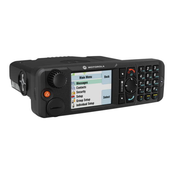
Details the items included in M1, M2, M3, and M4 radio models.
Sales Model Nomenclature
Explains the structure of sales model numbers and their positions.
Mobile Terminal Model Information
Details type, sales model, region, and short description for MTC953DE.
Model Specifications
Provides technical specifications like ETSI, temperature, power, GNSS, Bluetooth, and Wi-Fi.
MXM600 Accessories-to-Model Chart
Lists antennas compatible with different MXM600 models (M1-M4).
Vehicle Preparation
General Guidelines for Radio Installation
Provides general guidelines for installing the radio in a vehicle according to manufacturer standards.
Disconnecting Your Radio Power Supply
Details the procedure for safely disconnecting the radio's power supply before installation.
Installing DC Power Cable
Provides instructions and precautions for installing the DC power cable correctly.
Radio Installation
MXM600 Dashboard Installation
Explains the dashboard installation process for the M1 model.
MXM600 Desktop Installation
Explains the desktop installation process for the M1 model.
MXM600 Remote Mount Installation
Introduces remote mount installation options for the radio.
Junction Box Installation
Introduces the data junction box for easy installation of remote configurations.
Installing the Trunnion
Instructions for installing the trunnion for mounting the terminal to various surfaces.
Top of Dash Mount
Shows how to mount the radio on the top of the dash.
Below Dash Mounting
Shows how to mount the radio below the dash.
Connectors and PIN Assignment
Transceiver Front – Pin Functions
Details pin functions for the transceiver front view connectors.
26-Pin Accessory Connector
Details the pin functions of the 26-pin accessory connector.
Connectors and Pin Assignment of Expansion Heads
Overview of connectors and pin assignments for various expansion heads.
Connector and Pin Assignment of the Dash/Desk Control Head
Details the MMP connector and pin assignments for dash/desk control heads.
Connector and Pin Assignment of IP54 or IP67 Remote Ethernet Control Head
Details MMP connector and pin assignments for IP54/IP67 RECH.
Connector and Pin Assignment for Cradle (Telephone Style Control Head)
Details connectors and pin assignments for the TSCH cradle.
External Equipment Installation
Vehicle Antenna Installation
Describes the installation of vehicle antennas for optimal performance and compliance.
Mobile Radio Operation and EME Exposure
Discusses mobile radio operation and human exposure to RF energy.
Selecting an Antenna Site
Guidelines for selecting optimal antenna sites for performance and compliance.
Installing the Antenna
Procedure for mounting and connecting the antenna correctly.
Installing External Speaker
Instructions for mounting and connecting an external speaker.
Service Information
Technical & Repair Support (for Contracted Customers Only)
Information on contacting Motorola Solutions for technical and repair support.
Parts Identification and Ordering
Guidance on identifying and ordering spare parts for Motorola Solutions products.
Service Information for APAC
Service Information for Americas
Warranty and Service Support
Warranty Period and Return Instructions
Defines warranty terms and instructions for product returns to Motorola Solutions.
How To Get Warranty Service
Explains the process for obtaining warranty service, including proof of purchase.
Product Specific Information for Digital Terminals Type MTC953DE
Equipment Electrical Ratings
Provides electrical ratings, including voltage, current, and frequency ranges for the MTC953DE.
Normal Load Conditions
Details normal operating load conditions, including RF power, audio power, and temperature.
Fuse Identification
Identifies fuses for power and ignition sense cables with ratings and part numbers.
Table of Contents
Save PDF
Print
Rename the bookmark
Delete bookmark?
Delete from my manuals?
Login
Sign In
OR
Sign in with Facebook
Sign in with Google
Upload manual
Upload from disk
Upload from URL
Need help?
Do you have a question about the M3 and is the answer not in the manual?
Questions and answers