Sign In
Upload
Manuals
Brands
Motorola Manuals
Cell Phone
M3
Motorola M3 Manuals
Manuals and User Guides for Motorola M3. We have
2
Motorola M3 manuals available for free PDF download: Installation Manual, User Manual
Motorola M3 Installation Manual (135 pages)
Brand:
Motorola
| Category:
Radio
| Size: 16 MB
Table of Contents
Table of Contents
2
List of Figures
5
List of Tables
8
Intellectual Property and Regulatory Notices
11
Legal and Compliance Statements
11
Installation Requirements for Compliance with Radio Frequency (RF) Energy Exposure Safety Standards
12
Safety Information
12
Notations Used in this Guide
13
Read Me First
13
Table 1: Special Notations
13
Chapter 1: Model Information and Accessories
14
Model Descriptions
14
Table 2: Radio Model Descriptions
14
Sales Model Nomenclature
15
Table 3: Sales Model Nomenclature
15
Table 4: Sales Models - Description of Position
15
Mobile Terminal Model Information
16
Table 5: Type and Model Numbers
16
Model Specifications
17
Table 6: General Specifications
17
Table 7: Receiver Specifications
18
MXM600 Accessories-To-Model Chart
19
Table 8: Transmitter Specifications
19
Table 9: Antennas
19
Table 10: Cables
20
Table 11: Transceiver Rear Connector
21
Table 12: Control Heads
22
Table 13: Control Heads Legacy
23
Table 14: Expansion Head Kits
25
Table 15: Junction Box
25
Table 16: Microphones
25
Table 17: Mounting (Control Head)
26
Table 18: Mounting (Transceiver)
26
Table 19: Desktop Mount
26
Table 20: Power Cables (to Mobile Terminal)
26
Table 21: Power Supplies
27
Table 22: Line Cords for Power Supply
27
Table 23: Programming or Data
27
Table 24: Push-To-Talk (PTT) Switches
28
Table 25: Speakers
28
Table 26: Telephone Style Control Head Identification
28
Table 27: Miscellaneous
28
Table 28: Serial Expansion Head Compatible Control Heads and Accessories
29
Chapter 2: Vehicle Preparation
32
General Guidelines for Radio Installation
32
Power Supply Requirements
32
Disconnecting Your Radio Power Supply
33
Installing DC Power Cable
33
Figure 1: Power Cabling Routing to the Engine Compartment
34
Table 29: Associated Components
34
Figure 2: Power Cable Assembly
35
Table 30: Associated Components
35
DC Power Cables
36
Installing Ignition Sense Cable
36
Table 31: DC Power Cables
36
Ignition Sense Cables
37
Figure 3: 26-Pin Accessory Connector (PMLN8541_)
37
Table 32: Associated Components
37
Table 33: Ignition Sense Cables
37
Chapter 3: Radio Installation
38
MXM600 Dashboard Installation
38
Installing Your Radio in an Automotive DIN Slot Dashboard
38
Mounting Your Radio in the Frame
38
Removing Your Radio from the DIN Frame
39
Figure 4: Radio with Mount Kit
39
Table 34: Radio with Mount Kit Annotations
39
MXM600 Desktop Installation
40
Planning Desktop Installation
40
Setting up Desktop Installation
40
Figure 5: Radio with Demount Tools
40
Figure 6: Typical Desktop Mounting
41
Table 35: Associated Components
41
MXM600 Remote Mount Installation
42
Figure 7: Expansion Heads
42
Figure 8: Remote Mount Installation with IP54 RECH or IP67 RECH and SREH
43
Table 36: Expansion Heads Description
43
Figure 9: Remote Mount Installation with TSCH and DEH
44
Table 37: Configurations - Graphics Description
44
Table 38: Associated Components for Remote Mount
44
Figure 10: Remote Mount Installation with IP54 or IP67 RECH
46
Figure 11: Remote Mount Installation with TSCH
46
Figure 12: Dual Control Head with Two RECH (IP54 or IP67)
47
Figure 13: Dual Control Head with Two TSCH
48
Figure 14: Dual Control Head with a Combination of IP54 or IP67 RECH, and TSCH
49
Figure 15: Multi-Radio Control Installation with IP54 or IP67 RECH
49
Figure 16: Multi-Radio Control Installation with TSCH
50
Table 39: Configurations - Graphics Description
50
Ethernet Cables
51
Figure 17: RJ50 Ethernet Cable for IP67 RECH
51
Table 40: Ethernet Cables
51
Figure 18: Remote Ethernet Cable
52
Figure 19: Remote Ethernet Cable, 40 M (PMKN4135_)
52
Table 41: Associated Components
52
Table 42: Associated Components
52
Installing the IP67 Ethernet Cable
53
Figure 20: Remote Ethernet Cable (PMKN4176_, PMKN4177_, and PMKN4178_)
53
Table 43: Associated Components
53
Installing the Remote Ethernet Control Head (RECH) Onto the Remote Mount Trunnion
54
Figure 21: Connecting the RJ50 Connector to the IP67 RECH
54
Figure 22: IP54 or IP67 RECH Installation with Remote Mount Trunnion
54
Table 44: Associated Components
54
Installing the Remote Ethernet Control Head (RECH) in a DIN Mount Bracket
55
Inserting the IP54 or IP67 Remote Ethernet Control Head with the DIN Mount Bracket into the DIN Frame
55
Figure 23: IP54 or IP67 RECH Installation with DIN Mount Bracket
55
Accessories Expansion Cable
56
Figure 24: IP54 or IP67 RECH Installation with DIN Mount Bracket into the DIN Frame
56
Figure 25: Accessories Expansion Cable with the Mobile Microphone Port (MMP)
57
Figure 26: Accessories Expansion Cable with the Mobile Microphone Port (MMP)
57
Table 45: Associated Components
57
Installing the Accessories Expansion Cable
58
Extra Accessories for the IP54 or IP67 Remote Ethernet Control Head, and Telephone Style Control Head
58
Figure 27: Accessories Expansion RECH Y-Cable
59
Table 46: Associated Components
59
Figure 28: Accessories Expansion TSCH Y-Cable
61
Table 47: Associated Components
61
Telephone Style Control Head
63
Figure 29: Telephone Style Control Head (TSCH) Cradle
63
Figure 30: Telephone Style Control Head Handset and Cradle
64
Figure 31: Telephone Style Control Head Unsupported Installation
64
Mounting TSCH Cradle Onto Slim Bracket
65
Figure 32: Slim Bracket
65
Figure 33: TSCH Cradle Rear View
66
Figure 34: TSCH Cradle Rear View with Slim Bracket
67
Table 48: Associated Components
67
Databox Expansion Head Installation
68
Databox Expansion Head Radio Without Control Head
68
Figure 35: TSCH Cradle Rear View with Attached Slim Bracket
68
Data Box Radio
69
Databox Expansion Head with Third-Party Control Head
69
Figure 36: Data Box Radio Interface
69
Table 49: Associated Components
69
MXM600 with IP67 Remote Control Head
70
Figure 37: Configuration with Two Control and Data Terminals
70
Table 50: Associated Components
70
Figure 38: Comparison of RECH Types
71
Table 51: Compatibility of IP67 Control Heads
71
Installing IP67 Remote Ethernet Control Head in a Motorcycle
72
Figure 39: Differentiation between TELCO IP67 Control Head and IP67 RECH
72
Table 52: Associated Components
72
Figure 40: Motorcycle Installation
73
Table 53: Motorcycle Installation Description
73
Figure 41: Upward Movement
74
Mechanical Parts List for IP67 Remote Mount Installation
75
Figure 42: Downward Movement
75
Figure 43: IP67 Remote Ethernet Control Head (RECH) Mounted in a Trunnion
75
Extra Connectivity to the IP67 Remote Ethernet Control Head
76
Junction Box Installation
76
Table 54: Mechanical Parts List for Installation
76
Figure 44: Junction Box Installation (Rear)
77
Figure 45: Junction Box Installation (Front)
77
Installing the Junction Box
78
Connecting Accessories to the Junction Box
78
Table 55: Junction Box Installation Description
78
Connectors on the Junction Box
79
Figure 46: Connectors on the Junction Box - Rear Panel
79
Table 56: Associated Components
79
Figure 47: Connectors on the Junction Box - Front Panel
80
Table 57: Associated Components
80
Connection Plan for the Junction Box Accessory Plug
81
Figure 48: Connection Plan for the Speaker
81
Figure 49: Connection Plan for the Emergency Switch
82
Figure 50: Connection Plan for the Ignition Sense Cable
83
Table 60: Associated Components
83
Installing the Ignition Sense Cable
84
Figure 51: Connection Plan for External Push-To-Talk (PTT)
84
Table 61: Associated Components
84
Connection Plan for Accessory Plug
85
Table 62: Connection Plan for Accessory Connector Kit
85
Installing the Trunnion
86
Figure 52: Terminal into Low or High Profile Trunnion (GLN7324_ / GLN7317_)
87
Figure 53: Terminal into Enhanced Trunnion Kit (PMLN8620_)
87
Table 63: Associated Components
87
Figure 54: Terminal into Key Locked Mount Trunnion (RLN4779_)
88
Figure 55: Top of Dash Mount
89
Table 64: Associated Components
89
Figure 56: below Dash Mounting
90
Table 65: Associated Components
90
Chapter 4: Connectors and PIN Assignment
91
Transceiver Front - Pin Functions
91
Figure 57: Transceiver Front View - Dash/Desk Control Head and Expansion Head Interface
91
Table 66: Transceiver Front View
91
Table 67: Transceiver Pin Assignment of the Enhanced Control Head Interface (12-Pins)
91
Table 68: Transceiver Pin Assignment of the Expansion Board Connector (40-Pins)
92
Table 69: Transceiver Pin Assignment of the Ethernet Connector (18-Pins)
93
Transceiver Rear Side
94
Figure 58: Location of Accessory Connector - Rear Side
94
Table 70: Transceiver Pin Assignment of the Enhanced Control Head Interface (6-Pins)
94
Table 71: 26-Pin Accessory Connector
94
Accessory Connection Plan
97
Figure 59: Accessory Connector
97
Figure 60: 26-Pin Accessory Connector (PMLN8541_)
97
Table 72: PMLN5072_ Accessory Connector Kit Items
97
Figure 61: 26-Pin Rear Connector with Pre-Crimped, Open-Ended Cable (PMKN4303_)
98
Figure 62: Connecting Diagrams
98
Connecting Accessories to 26-Pin Connector
99
Cabled 26-Pin Connector
99
Figure 63: 26-Pin Rear Connector with Pre-Crimped, Open-Ended Cable and Dust Cover
99
Performing Re-Crimp Procedure Using Rear Accessories Connector
100
Figure 64: Dust Cover Installation
100
Connectors and Pin Assignment of Expansion Heads
101
Figure 65: Single Remote Expansion Head - Front View and Connector Location
101
Figure 66: Dual Remote Expansion Head - Front View and Connector Location
101
Table 73: Associated Components
101
Figure 67: Databox Expansion Head - Front View and Connector Location
102
Table 74: Associated Components
102
Table 75: Associated Components
102
10-Pin RJ50 Connector for Control Head
103
25-Pin Subd Connector
103
Table 76: 10-Pin RJ50 Ethernet Connector Pins
103
9-Pin Subd Connector
104
Table 77: 25-Pin Subd Connector Pins
104
10-Pin RJ50 Connector for SIM or Ethernet
105
Table 78: 9-Pin Subd Connector Pins
105
Table 79: Pin Assignment for the Third RJ50 Port (SIM/ETH)
105
Connector and Pin Assignment of the Dash/Desk Control Head
106
Figure 68: Mobile Microphone Port (MMP) Connector of the Dash/Desk Control Head
106
Table 58: Associated Components
106
Table 80: Associated Components
106
Table 81: MPP Connector of the Dash/Desk Control Head Functions
106
Connector and Pin Assignment of IP54 or IP67 Remote Ethernet Control Head
107
Figure 69: View of the IP54 or IP67 Remote Ethernet Control Head (RECH) with Mobile Microphone Port (MMP) Connector
107
Table 59: Associated Components
107
Table 82: Associated Components
107
Table 83: MMP Connector of the IP54 or IP67 RECH Functions
107
Figure 70: IP54 RECH - Rear Connectors
108
Figure 71: IP67 RECH - Rear Connectors
109
Table 84: Associated Components
109
Table 85: 10-Pin Ethernet Connector
109
Table 86: 25-Pin Back Connector
110
Connecting Cables
111
IP67 Remote Ethernet Control Head (RECH) Cable
111
Figure 72: IP67 RECH Ethernet Cable
111
Table 87: IP67 RECH Ethernet Cable Description
111
Motorcycle Mount TELCO Cable
112
Remote Mount Ethernet Cables
112
Accessories Expansion Cable
112
Figure 73: Motorcycle Remote Control Head (TELCO) Cable
112
Figure 74: Remote Mount Ethernet Cables
112
Figure 75: Accessories Expansion Cable, PMKN4029_ or PMKN4056
113
Figure 76: Accessories Expansion Cable, PMKN4429_ or PMKN4456
113
Table 88: Associated Components
113
Table 89: Accessories Expansion Cable - Connections
113
Connector and Pin Assignment for Cradle (Telephone Style Control Head)
115
Figure 77: View of the Telephone Style Control Head Cradle (TSCH)
115
Table 90: Pin Assignment of the 10-Pin Audio Connector - TSCH
115
Ethernet Cables
116
Figure 78: Mobile to Control Head Ethernet Cable Pin Diagram
116
Table 91: Pin Assignment of the 10-Pin RJ50 Connector - Telephone Style Control Head
116
Remote Ethernet Control Head Y-Cable (Accessories Expansion Cable)
117
Figure 79: Mobile to Mobile Ethernet Cable Pin Diagram
117
Figure 80: RECH Y-Cable Pin Diagram
117
Telephone Style Control Head Y-Cable (Accessories Expansion Cable)
118
Radio-To-Junction Box
118
Figure 81: TSCH Y-Cable Pin Diagram
118
Figure 82: Connecting Cable - Radio-To-Junction Box
119
Databox Expansion Head Radio-To-Data Device
120
Figure 83: Standardized RS232 Cable
120
Databox Expansion Head Radio-To-Fist Microphone
120
Operation
120
Making Connections
120
Removing the Existing Coiled Cord Cable
121
Figure 84: Pin Assignment of Cable from Accessory Connector to Microphone Housing
121
Table 92: Pin Assignment of Cable from Accessory Connector to Microphone Housing
121
Cables to Provision AIE/E2E Keys
122
Figure 85: Active Data Cable PMKN4104
122
Table 93: Associated Components
122
Table 94: Pin Assignment - Active Data Cable PMKN4104
122
Chapter 5: External Equipment Installation
123
Vehicle Antenna Installation
123
Mobile Radio Operation and EME Exposure
123
Selecting an Antenna Site
123
Installing the Antenna
124
Figure 86: Connections to the Rear Side of Your Radio
124
Completing Radio Installation
125
Installing External Speaker
125
Table 95: Associated Components
125
Figure 87: External Speaker Trunnion Bracket
126
Appendix A: Service Information
127
Contact Details
127
Parts Identification and Ordering
127
Appendix B: Service Information for APAC
128
Technical Support
128
Table 96: Service Information - Telephone Numbers and Addresses of the Asia and Pacific Motorola Solutions Centers
128
Piece Parts
130
Appendix C: Service Information for Americas
131
Warranty and Repairs
131
Table 97: Service Information - Telephone Numbers and Addresses of Latin America Radio Support Centers
131
Table 98: Service Information - Telephone Numbers and Addresses of Latin America Motorola Solutions Centers
131
Appendix D: Warranty and Service Support
133
Appendix E: Product Specific Information for Digital Terminals Type MTC953DE
134
Table 99: Equipment Electrical Ratings
134
Table 100: Normal Load Conditions
134
Table 101: Fuse Identification
135
Advertisement
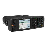
Motorola M3 User Manual (92 pages)
Motorola V2288: User Guide
Brand:
Motorola
| Category:
Cell Phone
| Size: 5 MB
Table of Contents
Understanding this Manual
4
Menu Navigation
5
Total Customer Satisfaction
7
Warranty Information
8
How to Get Warranty Service
8
What Is Not Covered by the Warranty
9
Safety and General Information
13
RF Operational Characteristics
13
Exposure to Radio Frequency Energy
13
Portable Personal Communicator Operation and EME Exposure
14
Electromagnetic Interference/Compatibility
14
Safety and General
15
Operational Warnings
15
European Union Directives Conformance Statement
16
Operational Cautions
16
About Your Phone, Battery and SIM Card
17
Earpiece Connector
18
Looking after Your Phone
18
Your Battery
19
Installing the Batteries
19
Battery Performance and Maintenance
20
Battery Indicators
22
Low Battery Warning
22
Your Sim Card
23
SIM Card Insertion/Removal
23
Making and Receiving Phone Calls
25
Switching the Phone on and off
25
Automatic Redial
26
Redialling the Last Number Called
26
Making a Phone Call
26
GSM Emergency Calls
27
Ending a Phone Call
28
Receiving a Phone Call
28
In-Call Menu
29
Call Holding and Call Waiting
31
Making a Conference Call
33
Transfer Call
34
Using the Options Menu
35
Access Internet
36
Using the Browser Menu
36
Setting up for Mobile Internet Access
37
Using the Soft Keys
37
Alphabetic Characters
39
Ending a Mobile Internet Session
40
Internet Service Alerts
40
Making and Receiving Calls During a Mobile Internet Session
40
Bookmark List
41
The Phone Book Menu
42
Using the Phone Book Menu
43
Find Entry by Location
45
Call Number
45
Modify Name or Number
45
Show Services
46
Last Ten Calls
46
My Phone Number(S)
47
Fixed Dialling
48
One-Touch Dial Setting
49
Call Related Features Menu
50
Show Battery Meter
50
Call Diverting
51
Restrict My Phone Number
51
Call Waiting
53
Call Barring
53
Change Bar Password
54
Messages Menu
55
Sms Messages
55
Cell Broadcast Messages
56
Call Voicemail
57
Received Messages
57
Outgoing Messages
58
Message Editor
58
Message Settings
59
Cell Broadcast
59
Expiry Period
60
Outgoing Message Type
60
Phone Setup Menu
61
Adjust Contrast
63
Require SIM Card PIN
63
Change SIM PIN2 Code
64
Unblocking Your Phone
64
New Security Code
64
Extended Menus
65
Language Selection
65
Master Clear
66
Network Selection Menu
67
Available Networks
68
Change Band
68
Network Search
68
Preferred Networks
69
Find New Network
70
Call Metering
71
Call Meters Menu
71
Show Call Charges
71
Set Audible Call Timers
72
Set In-Call Display
72
Show Call Timers
72
Call Charge Settings
73
Lifetime Timer
74
Automatic Answer
75
Accessory Setup Menu
75
Using the Quick Access Menu
77
Battery Meter
78
Lock Now
78
Call Voicemail
79
Using the Fm Radio
81
What to Do if
85
Message Editor
78
Advertisement
Related Products
Motorola M3097
MOTOROLA M3188
MOTOROLA M3688
MOTOROLA M3588
MOTOROLA M3288
MOTOROLA M3888
MOTOROLA M3788
Motorola M3682
MOTOROLA MT870
Motorola MOTO QA1
Motorola Categories
Cell Phone
Two-Way Radio
Baby Monitor
Cordless Telephone
Radio
More Motorola Manuals
Login
Sign In
OR
Sign in with Facebook
Sign in with Google
Upload manual
Upload from disk
Upload from URL