Table of Contents
Advertisement
Quick Links
SERVICE MANUAL
Input Method
Input Circuit
Input Impedance
Input Terminal
Operation
Speaker Terminals
Regulated Output*
Frequency Characteristics
Dumping Factor
Channel Separation
High Frequency Distortion
Rate
Residual Noise Voltage
(IHF:A. Input Short-Circuit)
Max. Amplitude
Indicator
Power Consumption
Weight
0 dBs = 0.775 V
* Distortion of 1 kHz high frequency is 0.1%.
MICROFILM
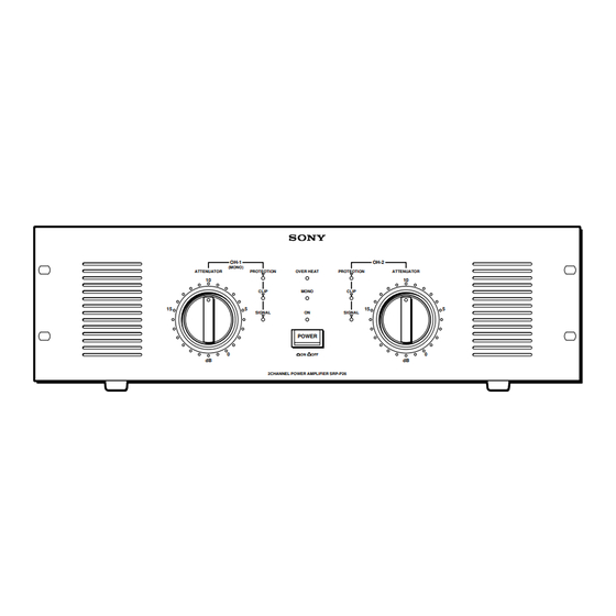
SRP-P26/P15
OH-1
OH-2
(MONO)
ATTENUATOR
PROTEOTION
OVER HEAT
PROTEOTION
ATTENUATOR
10
10
CLIP
MONO
CLIP
15
5
15
SIGNAL
ON
SIGNAL
POWER
0
ON
OFF
dB
dB
2CHANNEL POWER AMPLIFIER SRP-P26
SPECIFICATIONS
SRP-P26
Balanced type
Electronic balanced circuit
Above 20 kΩ
XLR-3-31 type /Barrier strips/Phone type
STEREO
MONO
Screw type terminal/
Neutrik NL4
250 W + 250 W (8 Ω)
400 W + 400 W (4 Ω)
800 W (8 Ω)
(When driving both
channels)
+ 0
20 Hz to 20 kHz
dB
– 1
Above 100
(8 Ω, 1 kHz)
Above 85 dB
(During 8 Ω, 1 kHz
regulated output)
Below 0.1%
Below 0.1%
(During 8 Ω,
(During 8 Ω,
100 W output)
200 W output)
Below 120 µV
Below 240 µV
31 dB
37 dB
SIGNAL Indicator
CLIP Indicator
PROTECTION Indicator
OVER HEAT Indicator
MONO Indicator
POWER Indicator
600 W
16 kg
AEP Model
5
0
SRP-P15
Balanced type
Electronic balanced circuit
Above 20 kΩ
XLR-3-31 type /Barrier strips/Phone type
STEREO
MONO
Screw type terminal/
Neutrik NL4
150 W + 150 W (8 Ω)
250 W + 250 W (4 Ω)
500 W (8 Ω)
(When driving both
channels)
+ 0
20 Hz to 20 kHz
dB
– 1
Above 100
(8 Ω, 1 kHz)
Above 85 dB
(During 8 Ω, 1 kHz
regulated output)
Below 0.1%
Below 0.1%
(During 8 Ω,
(During 8 Ω,
100 W output)
200 W output)
Below 120 µV
Below 240 µV
31 dB
37 dB
SIGNAL Indicator
CLIP Indicator
PROTECTION Indicator
OVER HEAT Indicator
MONO Indicator
POWER Indicator
400 W
15 kg
POWER AMPLIFIER
E Model
Advertisement
Table of Contents

Related Manuals for Sony SRP-P15 E


Summarization of Contents
Safety Information
Safety-Related Component Warning
Highlights critical components for safe operation and replacement guidelines.
Safety Check-out Procedure
Outlines essential safety checks to perform after repairs before release.
Names and Functions of Parts
Front Panel Controls and Indicators
Identifies and explains front panel controls, indicators, and their functions.
Operational Cautions
Provides important warnings and advice for proper operation and troubleshooting.
Connection Guide
Pre-Connection Precautions
Essential safety and procedural advice before connecting the unit.
Connection Examples (Stereo and Mono)
Illustrates typical connection setups for stereo and mono BTL configurations.
Disassembly Procedures
Upper Case Disassembly
Instructions for removing the upper section of the unit's enclosure.
Front Panel Disassembly
Instructions for disassembling the front panel assembly and its components.
Internal Board Disassembly
PS Board Disassembly
Instructions for disassembling the power supply board.
Main Internal Board Disassembly
Instructions for disassembling main internal circuit boards (A-CLASS, MAIN, TH).
Additional Board Disassembly
Speaker, Input, Jack Board Disassembly
Instructions for disassembling speaker, input, and jack circuit boards.
Circuit Board Location Overview
Visual map showing the location of all circuit boards within the unit.
Electrical Adjustments
Bias and DC Offset Adjustment
Procedure for setting bias and confirming DC offset for optimal performance.
Schematic Diagrams
Block Diagram
High-level overview of the amplifier's functional blocks and signal flow.
Printed Wiring Layouts (Main Boards)
Shows the physical component placement on main internal circuit boards.
Circuit Diagrams (Main Boards)
Detailed schematics for main internal circuit boards.
Printed Wiring Layouts (PS, LED, SW, T1, T2, TH Boards)
Shows the physical component placement on power supply and other boards.
Circuit Diagrams (PS, LED, SW, T1, T2, TH Boards)
Detailed schematics for power supply and other circuit boards.
Repair Parts List
Front Panel Section Parts
Lists replacement parts for the front panel assembly.
Heat Sink Section Parts
Lists replacement parts for the heat sink and associated components.
Rear Panel Section Parts
Lists replacement parts for the rear panel and connector assemblies.
Electrical Parts List
Main Board Electrical Parts
Lists components (transistors, capacitors, resistors, ICs) for the main board.
PS Board Electrical Parts
Lists components (diodes, capacitors, transistors, ICs) for the power supply board.
A-CLASS, T1, T2 Board Electrical Parts
Lists electrical components for A-CLASS, T1, and T2 circuit boards.
TH, INPUT, JACK Board Electrical Parts
Lists electrical components for TH, INPUT, and JACK circuit boards.
JACK, LED, SP, SW, VOL1, VOL2 Board Electrical Parts
Lists electrical components for JACK, LED, SP, SW, VOL1, and VOL2 circuit boards.
Miscellaneous, Accessories, and Hardware Parts
Lists miscellaneous parts, accessories, packing materials, and hardware.
Need help?
Do you have a question about the SRP-P15 E and is the answer not in the manual?
Questions and answers