Table of Contents
Advertisement
SERVICE MANUAL
Ver 1.0 2001.04
Amplifier section
DIN power output
TA-FE570:
TA-FE370:
Frequency response
PHONO (20 Hz - 20 kHz): RIAA equalization curve
TUNER, CD, AUX, TAPE1/DAT, TAPE2/MD:
S/N (network A)
PHONO:
TUNER, CD, AUX, TAPE1/DAT, TAPE2/MD:
Output voltage/impedance
RECOUT:
PHONES:
Speakers impedance 4 - 16 ohms
Damping factor
Sony Corporation
9-873-838-11
2001D0500-1
Home Audio Company
C 2001.4
Shinagawa Tec Service Manual Production Group
TA-FE370/FE570
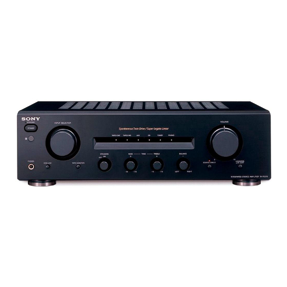
Photo: TA-FE570 (BLACK)
SPECIFICATIONS
110 W + 110 W
(4 ohms at 1 kHz)
70 W + 70 W
(4 ohms at 1 kHz)
±1.0 dB
+
0
7 Hz - 70 kHz
dB
–
3
80 dB
105 dB
200 mV, 1 kilohm
5 mW (at 8 ohms)
80 (8 ohms, 1 kHz)
INTEGRATED STEREO AMPLIFIER
General
System
Power amplifier with all stages directly coupled
Preamplifier:
Low-noise, equalizer
amplifier
Power requirements
230 V AC, 50/60 Hz
Power consumption
TA-FE570:
190 W
TA-FE370:
160 W
0.6 W
(In standby mode)
Dimensions (approx.) (w/h/d)
430 x 135 x 310 mm
incl. projecting parts and
controls
Mass (approx.)
TA-FE570:
6.5 kg
TA-FE370:
5.5 kg
Supplied accessories
Remote commander (remote) RM-S325 (1)
Sony batteries R6 (size-AA) (2)
Design and specifications are subject to change
without notice.
AEP Model
UK Model
Advertisement
Table of Contents

Related Manuals for Sony TA-FE370


Summary of Contents for Sony TA-FE370
-
Page 1: Service Manual
Speakers impedance 4 - 16 ohms Supplied accessories Damping factor 80 (8 ohms, 1 kHz) Remote commander (remote) RM-S325 (1) Sony batteries R6 (size-AA) (2) Design and specifications are subject to change without notice. INTEGRATED STEREO AMPLIFIER Sony Corporation 9-873-838-11... -
Page 2: Table Of Contents
LINE WITH MARK 0 ON THE SCHEMATIC DIAGRAMS AND IN THE PARTS LIST ARE CRITICAL TO SAFE OPERATION. REPLACE THESE COMPONENTS WITH SONY PARTS WHOSE PART NUMBERS APPEAR AS SHOWN IN THIS MANUAL OR IN SUPPLEMENTS PUB- LISHED BY SONY. -
Page 3: General
TA-FE370/FE570 SECTION 2 This section is extracted from instruction manual. GENERAL LOCATION OF CONTROLS • Front Panel • Back Panel AC OUTLET SWITCHED 100W MAX SPEAKERS IMPEDANCE USE 4 - 16 Ω PHONO TUNER TAPE2/MD TAPE1/DAT RECOUT RECOUT EON CONTROL –... -
Page 4: Disassembly
TA-FE370/FE570 SECTION 3 DISASSEMBLY • This set can be disassembled in the order shown below. 3-1. DISASSEMBLY FLOW 3-2. CASE (Page 4) 3-3. FRONT PANEL ASSY (Page 5) 3-4. MAIN BOARD (Page 5) Note: Follow the disassembly procedure in the numerical order given. -
Page 5: Front Panel Assy
TA-FE370/FE570 3-3. FRONT PANEL ASSY 3 screw (BVTP3 × 8) 1 connector (CN811) 4 harness 1 connector (CN812) 5 two screws 2 wire (flat type) (15 core) (BVTP3 × 8) (CN815) 7 front panel assy 6 four screws (BVTP3 × 8) 3-4. - Page 6 TA-FE370/FE570 MEMO...
-
Page 7: Diagrams
TA-FE370/FE570 SECTION 4 DIAGRAMS 4-1. NOTE FOR PRINTED WIRING BOARDS AND SCHEMATIC DIAGRAMS • Circuit Boards Location Note on Printed Wiring Board: Note on Schematic Diagram: STANDBY board • All capacitors are in µF unless otherwise noted. pF: µµF • X : parts extracted from the component side. -
Page 8: Printed Wiring Board - Main Board
TA-FE370/FE570 4-2. PRINTED WIRING BOARD – MAIN Board – • See page 7 for Circuit Boards Location. • Semiconductor Location Ref. No. Location J102 J103 TM301 J101 D101 TAPE2/MD TAPE1/DAT D301 PHONO TUNER SPEAKERS RECOUT RECOUT IMPEDANCE USE4 – 16Ω... -
Page 9: Schematic Diagram - Main Board
TA-FE370/FE570 4-3. SCHEMATIC DIAGRAM – MAIN Board – • See page 14 for IC Block Diagrams. C301 R302 R314 0.22 IC301(2/2) L301 C302 R301 C303 470p 100p STK4211MK2 (FE370) STK4221MK2 (FE570) (CHASSIS) C314 POWER AMP PHONO EQ AMP C313 J101... -
Page 10: Printed Wiring Boards - Control/Speaker Sw/Volume Boards
TA-FE370/FE570 4-4. PRINTED WIRING BOARDS – CONTROL/SPEAKER SW/VOLUME Boards – • See page 7 for Circuit Boards Location. (Page 8) MAIN BOARD CN815 CONTROL BOARD VOLUME BOARD POWER PHONO TUNER TAPE2/MD TAPE1/DAT BOARD INPUT CN807 SELECTOR (Page 12) RV202 –1 VOLUME –2... -
Page 11: Schematic Diagram - Control/Speaker Sw/Volume Boards
TA-FE370/FE570 4-5. SCHEMATIC DIAGRAM – CONTROL/SPEAKER SW/VOLUME Boards – • • See page 7 for Waveform. See page 14 for IC Block Diagram. (FE570) D821 SEL5823A-TP15 R835 EON LINK R831 S803 S205 SPEAKERS S803 Q812,813 C319 EON LINK 0.01 R838... -
Page 12: Printed Wiring Boards - Ac Outlet/Headphone/Loudness/Power Sw/Standby Boards
TA-FE370/FE570 4-6. PRINTED WIRING BOARDS – AC OUTLET/HEADPHONE/LOUDNESS/POWER SW/STANDBY Boards – • See page 7 for Circuit Boards Location. • Semiconductor Location Ref. No. Location POWER SW BOARD (AEP) AC OUTLET BOARD D822 D911 D912 D913 D914 STANDBY D915 D916 –1... -
Page 13: Schematic Diagram
TA-FE370/FE570 4-7. SCHEMATIC DIAGRAM – AC OUTLET/HEADPHONE/LOUDNESS/POWER SW/STANDBY Boards – (AEP) POWER REMOTE CONTROL POWER RECEIVER TRANSFORMER R833 2.2k IC803 (MAIN) NJL64H400A CN807 D822 SEL5223S T2.5AL -TP15 250V STANDBY STBY T1.6AL CN4–6 (Page 9) 250V AC OUTLET (FE370) SIRCS SWITCHED 100W MAX 0.0047... -
Page 14: 4-8. Ic Pin Function Description
POWER switch (S1) input terminal “H”: power on – CONTROL Board – TAPE1 MONITOR switch (S802) input terminal “H” input when key pressing IC802 BA6208 (Used for the TA-FE570) TA-FE370: Not used (fixed at “L”) SIRCS Sircs signal input from the remote control receiver (IC803) MUTE Audio line muting on/off control signal output “H”: muting on... -
Page 15: Exploded Views
TA-FE370/FE570 SECTION 5 EXPLODED VIEWS NOTE: • -XX and -X mean standardized parts, so they • Items marked “*” are not stocked since they The components identified by mark 0 or dotted line with mark may have some difference from the original are seldom required for routine service. -
Page 16: Front Panel Section
TA-FE370/FE570 5-2. FRONT PANEL SECTION supplied with S801 supplied with S205 supplied with RV202 supplied with RV201, 203, 204 Ref. No. Part No. Description Remark Ref. No. Part No. Description Remark X-4953-702-1 PANEL, FRONT ASSY (BLACK) (FE570) 1-681-421-11 POWER SW BOARD X-4953-703-1 PANEL, FRONT ASSY (BLACK) (FE370) 4-951-620-01 SCREW (2.6X8), +BVTP... -
Page 17: Chassis Section
TA-FE370/FE570 5-3. CHASSIS SECTION not supplied not supplied not supplied not supplied not supplied The components identified by mark 0 or dotted line with mark 0 are critical for safety. Replace only with part number specified. Ref. No. Part No. -
Page 18: Electrical Parts List
TA-FE370/FE570 SECTION 6 AC OUTLET ELECTRICAL PARTS LIST CONTROL NOTE: • Due to standardization, replacements in the • Items marked “*” are not stocked since they The components identified by mark 0 or dotted line with mark parts list may be different from the parts speci- are seldom required for routine service. - Page 19 TA-FE370/FE570 CONTROL HEADPHONE LOUDNESS MAIN Ref. No. Part No. Description Remark Ref. No. Part No. Description Remark R208 1-247-874-11 CARBON 1/4W < SWITCH > R251 1-249-434-11 CARBON 1/4W R252 1-249-421-11 CARBON 2.2K 1/4W S202 1-571-828-11 SWITCH, PUSH (1 KEY) (SOURCE DIRECT)
- Page 20 TA-FE370/FE570 MAIN Ref. No. Part No. Description Remark Ref. No. Part No. Description Remark C301 1-126-964-11 ELECT 10uF C905 1-126-968-11 ELECT 100uF C302 1-162-290-31 CERAMIC 470PF (FE370) C303 1-162-282-31 CERAMIC 100PF C905 1-128-576-11 ELECT 100uF C305 1-126-933-11 ELECT 100uF (FE570)
- Page 21 TA-FE370/FE570 MAIN Ref. No. Part No. Description Remark Ref. No. Part No. Description Remark L351 1-420-872-00 COIL, AIR-CORE R176 1-249-441-11 CARBON 100K 1/4W R207 1-249-425-11 CARBON 4.7K 1/4W < TRANSISTOR > R257 1-249-425-11 CARBON 4.7K 1/4W Q101 8-729-141-26 TRANSISTOR 2SC3622A-LK...
- Page 22 TA-FE370/FE570 MAIN POWER SW SPEAKER SW STANDBY VOLUME Ref. No. Part No. Description Remark Ref. No. Part No. Description Remark R907 1-260-328-11 CARBON 1/2W 1-564-321-00 PIN, CONNECTOR 2P (FE370) 1-564-321-00 PIN, CONNECTOR 2P R907 1-260-330-11 CARBON 1.5K 1/2W CN902 1-691-767-11 PLUG (MICRO CONNECTOR) 5P...
- Page 23 TA-FE370/FE570 MEMO...
-
Page 24: Revision History
TA-FE370/FE570 REVISION HISTORY Clicking the version allows you to jump to the revised page. Also, clicking the version at the upper right on the revised page allows you to jump to the next revised page. Ver. Date Description of Revision...
Need help?
Do you have a question about the TA-FE370 and is the answer not in the manual?
Questions and answers