Table of Contents
Advertisement
Quick Links
SERVICE MANUAL
Input Method
Input Circuit
Input Impedance
Input Terminal
Operation
Speaker Terminals
Regulated Output*
Frequency Characteristics
Dumping Factor
Channel Separation
High Frequency Distortion
Rate
Residual Noise Voltage
(IHF:A. Input Short-Circuit)
Max. Amplitude
Indicator
Power Consumption
Weight
0 dBs = 0.775 V
* Distortion of 1 kHz high frequency is 0.1%.
MICROFILM
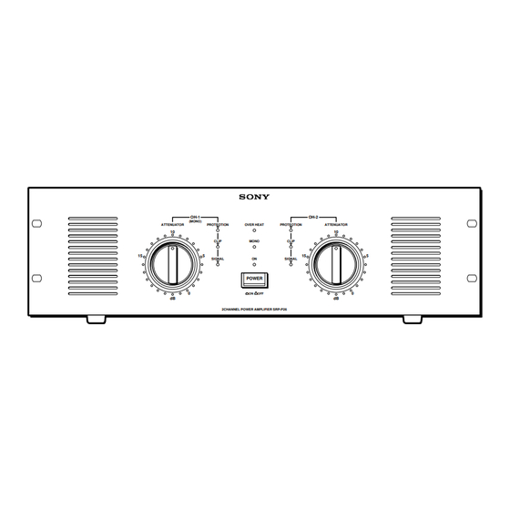
SRP-P26/P15
OH-1
OH-2
(MONO)
ATTENUATOR
PROTEOTION
OVER HEAT
PROTEOTION
ATTENUATOR
10
10
CLIP
MONO
CLIP
15
5
15
SIGNAL
ON
SIGNAL
POWER
0
ON
OFF
dB
dB
2CHANNEL POWER AMPLIFIER SRP-P26
SPECIFICATIONS
SRP-P26
Balanced type
Electronic balanced circuit
Above 20 kΩ
XLR-3-31 type /Barrier strips/Phone type
STEREO
MONO
Screw type terminal/
Neutrik NL4
250 W + 250 W (8 Ω)
400 W + 400 W (4 Ω)
800 W (8 Ω)
(When driving both
channels)
+ 0
20 Hz to 20 kHz
dB
– 1
Above 100
(8 Ω, 1 kHz)
Above 85 dB
(During 8 Ω, 1 kHz
regulated output)
Below 0.1%
Below 0.1%
(During 8 Ω,
(During 8 Ω,
100 W output)
200 W output)
Below 120 µV
Below 240 µV
31 dB
37 dB
SIGNAL Indicator
CLIP Indicator
PROTECTION Indicator
OVER HEAT Indicator
MONO Indicator
POWER Indicator
600 W
16 kg
AEP Model
5
0
SRP-P15
Balanced type
Electronic balanced circuit
Above 20 kΩ
XLR-3-31 type /Barrier strips/Phone type
STEREO
MONO
Screw type terminal/
Neutrik NL4
150 W + 150 W (8 Ω)
250 W + 250 W (4 Ω)
500 W (8 Ω)
(When driving both
channels)
+ 0
20 Hz to 20 kHz
dB
– 1
Above 100
(8 Ω, 1 kHz)
Above 85 dB
(During 8 Ω, 1 kHz
regulated output)
Below 0.1%
Below 0.1%
(During 8 Ω,
(During 8 Ω,
100 W output)
200 W output)
Below 120 µV
Below 240 µV
31 dB
37 dB
SIGNAL Indicator
CLIP Indicator
PROTECTION Indicator
OVER HEAT Indicator
MONO Indicator
POWER Indicator
400 W
15 kg
POWER AMPLIFIER
E Model
Advertisement
Table of Contents


Need help?
Do you have a question about the SRP-P26 AEP and is the answer not in the manual?
Questions and answers