
Related Manuals for Delta DVP04DA-SL


Summary of Contents for Delta DVP04DA-SL
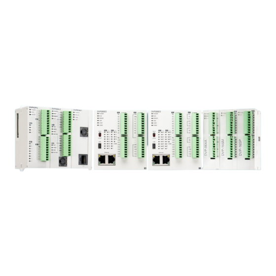
- Page 1 Digitized Automation for a Changing World DVP-SE2 Series Hardware and Operation Manual www.deltaww.com...
-
Page 2: Revision History
DVP-SE2 Series Hardware and Operation Manual Revision History Ve r s i o n R e v i s i o n D a t e T h e f i r s t v e r s i o n w a s p u b l i s h e d . -
Page 3: Table Of Contents
Table of Contents Chapter 1 Product Introduction 1.1 Introduction..................1-2 1.1.1 Related Manuals………………………………………………………………………………………… 1-2 1.1.2 DVP-SE2 Series CPU Modules and Their Extension Modules……..…………….1-2 1.2 Overview....................1-6 1.3 Characteristics ..................1-7 Chapter 2 Specifications and System Configuration DVP-SE2 Series .................. 2-2 2.1.1 General Specifications .............. - Page 4 Flow Chart of Low Voltage Process ............ 4-9 Appedix A EMC Standards EMC Standards for an SE2 Series System ..........A-2 A.1.1 DVP-SE2 Series System EMC Standards ..........A-2 A.1.2 Installation Instructions to meet EMC Standards ........ A-3 A.1.3 Cables ..................A-3 Appedix B Maintenance and Inspection Cautions ....................
-
Page 5: Chapter 1 Product Introduction
Chapter 1 Product Introduction Table of Contents 1.1 Introduction ....................1-2 1.1.1 Related Manuals……………………………………………………………………………………………………… 1-2 1.1.2 DVP-SE2 Series CPU Modules and Their Extension Modules………………………………….1-2 1.2 Overview ......................1-6 1.3 Characteristics ....................1-7 1 - 1... -
Page 6: Introduction
D V P - S E 2 S e r i e s H a r d w a r e a n d O p e r a t i o n M a n u a l Introduction This manual introduces the slim-type DVP-SE2 Series PLC CPU; their functions, electrical specifications, hardware configuration, appearances, dimensions, as well as wiring and so forth are presented here. Refer to DVP Series Module Manual for more information on the extension I/O modules of DVP-SE2 Series PLC CPU. - Page 7 C h a p t e r 1 P r o d u c t I n t r o d u c t i o n Classification Model Name Description 24 VDC powered CPU module Transistor, PNP output, 1x Ethernet port (dual-interface with Switch function), DVP28SE211S 2x RS-485 ports, 1x USB &...
- Page 8 D V P - S E 2 S e r i e s H a r d w a r e a n d O p e r a t i o n M a n u a l Classification Model Name Description 4 channel analog inputs (differential)
- Page 9 C h a p t e r 1 P r o d u c t I n t r o d u c t i o n Classification Model Name Description 2 channels DVP02LC-SL 20-bit resolution: 0~6mV/V Left-side high-speed load cell module 1 channel DVP01LC-SL 20-bit resolution: 0~6mV/V...
-
Page 10: Overview
CANopen Master module; 1Mbps communication module DVPSCM12-SL RS-485/RS-422 series communication module; 460kbps DVPSCM52-SL BACnet MS/TP Slave module; 460kbps Overview DVP-SE2 is slim-type advanced controller. With up to 4-axis (pulse) for positioning outputs and Delta Servos, they can 1 - 6... -
Page 11: Characteristics
Create DVP-SE2 PLC CPU hardware configuration by software. Also restore or back up a system rapidly through the built-in SD interface in this DVP Series PLC CPU. This manual introduces the basic operation and help you familiarize yourself with DVP-SE2 Series. Characteristics (1) High efficiency A 32-bit high-speed processor is used. - Page 12 (5) Strong function block Both standard IEC61131-3 function blocks and convenient functions blocks provided by Delta Electronics, Inc. are supported. You can use function blocks for frequently used programs for greater structure and convenience.
- Page 13 DVP PLC CPU module. (7) Serial control interface (RS-485 and CAN) with multiple functions DVP-SE2 Series CPU modules provide two RS-485 serial control interfaces, COM1 and COM2, which can be set as a either master or slave.
- Page 14 Chapter 2 Specifications and System Configuration Table of Contents 2.1 DVP-SE2 Series ....................2-2 2.1.1 General Specifications ................2-2 2.1.2 CPU Module Specifications................2-3 2.1.2.1 Functional Specifications ..............2-3 2.1.2.2 Electrical specifications ................ 2-4 2.1.2.3 CPU Module Profiles ................2-6 2.1.2.4...
-
Page 15: Chapter 2 Specifications And System Configuration
C h a p t e r 2 S p e c i f i c a t i o n s a n d S y s t e m C o n f i g u r a t i o n DVP-SE2 Series 2.1.1... -
Page 16: Cpu Module Specifications
C h a p t e r 2 S p e c i f i c a t i o n s a n d S y s t e m C o n f i g u r a t i o n 2.1.2 CPU Module Specifications 2.1.2.1... -
Page 17: Electrical Specifications
DV P- S E 2 S e r i e s H a r d w a r e a n d O p e r a t i o n M a n u a l 2.1.2.2 Electrical specifications Model DVP28SE211T Item... - Page 18 C h a p t e r 2 S p e c i f i c a t i o n s a n d S y s t e m C o n f i g u r a t i o n Electrical specifications for the outputs on DVP-SE2 Series ...
-
Page 19: Cpu Module Profiles
DV P- S E 2 S e r i e s H a r d w a r e a n d O p e r a t i o n M a n u a l 2.1.2.3 CPU Module Profiles 80.00 9.90 3.40 62.60... -
Page 20: Cpu Module Input/Output Terminals
C h a p t e r 2 S p e c i f i c a t i o n s a n d S y s t e m C o n f i g u r a t i o n Name Description Provides Ethernet Switch communication interface for dual RJ45 communication... -
Page 21: Power Supply Module
DV P- S E 2 S e r i e s H a r d w a r e a n d O p e r a t i o n M a n u a l 2.1.3 Power Supply Module 2.1.3.1 General Specifications DVPPS01/DVPPS02/DVPPS05... -
Page 22: Power Supply Module Profiles
C h a p t e r 2 S p e c i f i c a t i o n s a n d S y s t e m C o n f i g u r a t i o n 2.1.3.2 Power Supply Module Profiles DVPPS01... - Page 23 DV P- S E 2 S e r i e s H a r d w a r e a n d O p e r a t i o n M a n u a l DVPPS05 140.00 121.60 Unit: mm Number...
-
Page 24: Chapter 3 Installing Hardware And Wiring
Grounding ..................3-9 3.1.5.3 Wiring Power Supply ................3-10 3.1.5.4 Power Consumption ................3-10 3.1.6 Wiring Digital Input Terminals on DVP-SE2 Series .........3-11 3.1.6.1 Direct Current Power Supply (24 VDC) ..........3-11 3.1.6.2 Relay Types ..................3-12 3.1.6.3 Open-collector Input Types ..............3-13 3.1.6.4... -
Page 25: Dvp-Se2 Series
3.1.1 DVP-SE2 Hardware Framework The DVP-SE2 series programmable logic controller is a small programmable logic control (PLC). The execution speed and memory capacity are increased. Use of function blocks is also supported. In order to meet more advanced application requirements, the DVP-ES3/EX3 series programmable logic controllers provide more flexible system extension framework. - Page 26 W ir in g C h a p t e r 3 I n s t a l l i n g H a r d w a r e a n d Optional components - extension modules Apart from the standard communication ports on a CPU module, the CPU module is equipped with I/O functions. Refer to section 1.1.2 for a selection of extension modules.
-
Page 27: Notes On Installation
D V P - S E 2 S e r i e s H a r d w a r e a n d O p e r a t i o n M a n u a l 3.1.2 Notes on Installation EN: System integrators shall be responsible for assembly of the control system and the safety of the system integration. -
Page 28: Installation
W ir in g C h a p t e r 3 I n s t a l l i n g H a r d w a r e a n d 3.1.3 Installation A PLC has to be installed in a closed control box. In order to ensure that the PLC radiates heat normally, the space between the PLC and the control box must be larger than 50 millimeters. -
Page 29: Link The Cpu Module And A Module
D V P - S E 2 S e r i e s H a r d w a r e a n d O p e r a t i o n M a n u a l 3.1.3.2 Link the CPU Module and a Module Step 1: Use a flat head screwdriver to open the side Step 2: Use a flat head screwdriver to release the I/O... -
Page 30: Wiring
W ir in g C h a p t e r 3 I n s t a l l i n g H a r d w a r e a n d 3.1.4 Wiring EN: Before installing or wiring a module, you must verify that the external power supply is turned off. ... -
Page 31: Connect Power Cables
D V P - S E 2 S e r i e s H a r d w a r e a n d O p e r a t i o n M a n u a l < 2 mm 6-8 mm 24-16 AWG Keep the input cables, output cables, and power cable separate from one another. -
Page 32: Grounding
W ir in g C h a p t e r 3 I n s t a l l i n g H a r d w a r e a n d Surge absorber DVPPS01 DVPPS02 Power Supply DVPPS05 100~240VAC Environment ... -
Page 33: Wiring Power Supply
D V P - S E 2 S e r i e s H a r d w a r e a n d O p e r a t i o n M a n u a l 3.1.5.3 Wiring Power Supply Con trol B ox SE 2... -
Page 34: Wiring Digital Input Terminals On Dvp-Se2 Series
62.5 Note: The total power consumption of the extension modules connected to the CPU module is limited to 36 W. 3.1.6 Wiring Digital Input Terminals on DVP-SE2 Series 3.1.6.1 Direct Current Power Supply (24 VDC) When the digital input signal is DC input, there are two DC input types, Sinking and Sourcing. See the definition below. -
Page 35: Relay Types
D V P - S E 2 S e r i e s H a r d w a r e a n d O p e r a t i o n M a n u a l 3.1.6.2 Relay Types Sinking ... -
Page 36: Open-Collector Input Types
W ir in g C h a p t e r 3 I n s t a l l i n g H a r d w a r e a n d 3.1.6.3 Open-collector Input Types Sinking (PNP input type) ... -
Page 37: Three-Wire Proximity Switch
D V P - S E 2 S e r i e s H a r d w a r e a n d O p e r a t i o n M a n u a l 3.1.6.5 Three-wire Proximity Switch Sinking ... -
Page 38: Wiring Digital Output Terminals On Dvp-Se2 Series
3.1.7 Wiring Digital Output Terminals on DVP-SE2 Series DVP-SE2 series PLCs output module is transistor type. When wiring the output terminals, pay attention to the connection of the common terminals. For transistor models (NPN), the output terminals Y0, Y1, Y2 and Y3 share the common terminal C0; Y4, Y5, Y6 and Y7 share the common terminal C1;... -
Page 39: Output Circuits (Transistor)
D V P - S E 2 S e r i e s H a r d w a r e a n d O p e r a t i o n M a n u a l 3.1.7.1 Output Circuits (Transistor) Transistor output ... -
Page 40: Wiring Dvp-Se2 Communication Ports
W ir in g C h a p t e r 3 I n s t a l l i n g H a r d w a r e a n d 3.1.8 Wiring DVP-SE2 Communication Ports R S-485 C A N U SB Ethernet... -
Page 41: Can Pins And Wiring
D V P - S E 2 S e r i e s H a r d w a r e a n d O p e r a t i o n M a n u a l 3.1.8.3 RS-485 Pins and Wiring RS-485 Pins ... -
Page 42: Chapter 4 Troubleshooting
12 4 Chapter 4 Troubleshooting Table of Contents Troubleshooting .................... 4-2 4.1.1 Basic Troubleshooting Steps ................ 4-2 4.1.2 Clear the Error States ................. 4-2 4.1.3 Troubleshooting SOP .................. 4-3 CPU Module Troubleshooting ................. 4-4 Error Code Table (Hex) .................. 4-5 Error Detection Devices ................. -
Page 43: Troubleshooting
(2) Check the following operational functions: Switch the RUN/STOP state. Check the settings for the DVP-SE2 Series to RUN/STOP Check and eliminate errors from external devices. Use the System Log function in ISPSoft to check system operation and logs. -
Page 44: Troubleshooting Sop
Ch a pt er 4 Tr o ub l es ho ot i ng 4.1.3 Troubleshooting SOP err or occur red B asi c Refe r to sect ion 4.1. 1 for tro ub le sh oo tin g ste p s Ba sic tro ubleshoo ting st eps d on e 1 .Re fer to se cti on 4.2 for tr ou bl esh o oti ng... - Page 45 The PLC CPU cannot read/write data, cannot and then starts blinking 0.2 seconds execute any communication nor operation. Contact Delta technical support again. The blinking pattern keeps team or the distributors for further help.
-
Page 46: Error Code Table (Hex)
Ch a pt er 4 Tr o ub l es ho ot i ng Description Solution When there are inputs, but the input indicator LEDs are OFF, Check the wiring of the input devices. Check that the power is properly supplied to the input terminals. If the power is properly supplied to the input terminal, there is probably an abnormality in the PLC’s input circuit. - Page 47 DV P- S E 2 S er i es Har d war e a n d O p er a t io n M an u a l Error code Description Solution 0503 Operand KnYm exceeds the valid range 0601 Operand bit device T exceeds the valid range 0604 Operand word device T register exceeds limit...
- Page 48 Ch a pt er 4 Tr o ub l es ho ot i ng Error code Description Solution C404 FOR-NEXT exceed 6 levels A circuit error occurs if a combination of STL / RET used between FOR and NEXT instructions is incorrectly specified. SRET / IRET used between FOR and NEXT C405 MC / MCR used between FOR and NEXT...
-
Page 49: Error Detection Devices
DV P- S E 2 S er i es Har d war e a n d O p er a t io n M an u a l Error code Description Solution PLC program - MCU unique ID is not matched. Note: PLC checks if the program can be stored. - Page 50 Ch a pt er 4 Tr o ub l es ho ot i ng Troubleshooting for Other Module Please refer to DVP series module manual for troubleshooting information on other modules. Flow Chart of Low Voltage Process Low voltage: when the 24VDC power supply voltage drops below 17.8V(with approximately 2% tolerance) for a duration exceeding 10ms.
-
Page 51: Appendix A Emc Standards
Appendix A EMC Standards Table of Contents EMC Standards for an SE2 Series System ............. A-2 A.1.1 DVP-SE2 Series System EMC Standards ............A-2 A.1.2 Installation Instructions to meet EMC Standards ..........A-3 A.1.3 Cables ...................... A-3 A - 1... -
Page 52: Emc Standards For An Se2 Series System
DV P- S E 2 S er i es Har d war e a n d O p er a t io n M an u a l EMC Standards for an SE2 Series System A.1.1 DVP-SE2 Series System EMC Standards The EMC standards that are applicable to DVP-SE2 series system are listed in the following tables. Port Frequency range... -
Page 53: Installation Instructions To Meet Emc Standards
A pp e nd ix A E MC St an dar ds Conducted immunity test Fast transient Radio frequency Environmental phenomenon High energy surge burst interference Reference standard IEC 61000-4-4 IEC 61000-4-5 IEC 61000-4-6 Interface/Port Specific interface/port Test level Test level Test level Shielded cable... -
Page 54: Appendix B Maintenance And Inspection
Appendix B Maintenance and Inspection Table of Contents Cautions ......................B-2 Daily Maintenance ..................B-2 B.2.1 Daily Inspection ..................B-3 Periodic Maintenance ..................B-4 B.3.1 Periodic Inspection ..................B-4 B - 1... -
Page 55: Cautions
DV P- S E 2 S er i es Har d war e a n d O p er a t io n M an u a l Cautions Observe the following precautions before performing maintenance and inspection. Incorrect or careless operation will lead to injury or equipment damage. -
Page 56: Daily Inspection
A pp e nd ix B Ma i nt e na nc e a n d Ins p ec t i on B.2.1 Daily Inspection Item Inspection Criterion Remedy Appearance Check visually. Dirt must not be present. Remove the dirt. Check whether the set Tighten the screws. -
Page 57: Periodic Maintenance
DV P- S E 2 S er i es Har d war e a n d O p er a t io n M an u a l Periodic Maintenance In addition to daily inspection, you should perform periodic maintenance depending on the actual operating environment. After making sure that the ambient environment and the PLC Series system conform to the cautions listed in Section B.1, perform the periodic inspection described below. - Page 58 Unit 2, Building A, 18-24 Ricketts Road, TEL: +39 039 8900365 Mount Waverley, Victoria 3149 Australia Mail: IA.au@deltaww.com Delta Greentech Elektronik San. Ltd. Sti. ( Turkey ) TEL: +61-1300-335-823 / +61-3-9543-3720 Şerifali Mah. Hendem Cad. Kule Sok. No:16 - A 34775 Ümraniye – İstanbul Americas Mail: Sales.IA.Turkey@deltaww.com...
Need help?
Do you have a question about the DVP04DA-SL and is the answer not in the manual?
Questions and answers