Table of Contents
Advertisement
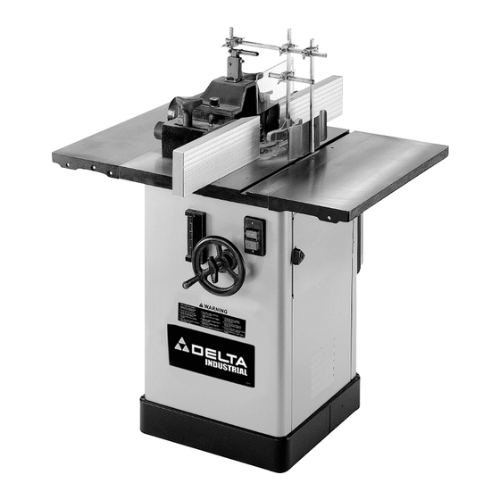
2-Speed Heavy-Duty
Wood Shaper
(Models 43-460 & 43-459)
PART NO. 432-02-651-0041 - 05-10-04
Copyright © 2004 Delta Machinery
To learn more about DELTA MACHINERY
visit our website at: www.deltamachinery.com.
For Parts, Service, Warranty or other Assistance,
1-800-223-7278 (
1-800-463-3582).
please call
In Canada call
Advertisement
Table of Contents

Related Manuals for Delta 43-460


Summary of Contents for Delta 43-460
- Page 1 2-Speed Heavy-Duty Wood Shaper (Models 43-460 & 43-459) PART NO. 432-02-651-0041 - 05-10-04 Copyright © 2004 Delta Machinery To learn more about DELTA MACHINERY visit our website at: www.deltamachinery.com. For Parts, Service, Warranty or other Assistance, 1-800-223-7278 ( 1-800-463-3582). please call...
-
Page 2: Safety Guidelines - Definitions
SAFETY GUIDELINES - DEFINITIONS This manual contains information that is important for you to know and understand. This information relates to protect- ing YOUR SAFETY and PREVENTING EQUIPMENT PROBLEMS. To help you recognize this information, we use the symbols to the right. Please read the manual and pay attention to these sections. Indicates an imminently hazardous situation which, if not avoided, will result in death or serious injury. -
Page 3: General Safety Rules
GENERAL SAFETY RULES FAILURE TO FOLLOW THESE RULES MAY RESULT IN SERIOUS INJURY. 1. FOR YOUR OWN SAFETY, READ THE INSTRUCTION MANUAL BEFORE OPERATING THE MACHINE. Learning the machine’s application, limitations, and specific hazards will greatly minimize the possibility of accidents and injury. - Page 4 ADDITIONAL SAFETY RULES FOR WOOD SHAPERS FAILURE TO FOLLOW THESE RULES MAY RESULT IN SERIOUS INJURY. DO NOT OPERATE THIS MACHINE UNTIL it is assembled and installed according to the instructions. OBTAIN ADVICE from your supervisor, instructor, or another qualified person if you are not familiar with the operation of this machine.
-
Page 5: Power Connections
FUNCTIONAL DESCRIPTION FOREWORD Delta Model 43-460 is a 5 HP, single phase, 230V wood shaping machine. It utilizes a Poly V-belt drive system that transmits more efficient torque to the spindle and has a capacity (under nut) of 5". UNPACKING AND CLEANING Carefully unpack the machine and all loose items from the shipping container(s). - Page 6 For your own safety, do not connect the machine to the power source until the machine is completely assembled, and you read and understand the entire instruction manual. ATTACHING SPINDLE RAISING AND LOWERING HANDWHEEL Insert the key (A) Fig. 1 into the slot in the spindle raising and lowering shaft (B). Place the handwheel (C) Fig.
- Page 7 ATTACHING TABLE INSERTS Three table inserts are provided for various size cutters (Fig. 8). The large insert is adjustable. To set it flush with the table: Remove the three slotted head screws (A) Fig. 8. Use a screwdriver to turn the three adjusting screws (B) Fig.8 until the insert is flush with the table.
- Page 8 ATTACHING ELECTRICAL BOX TO CABINET The tool is shipped with the starter box wired to the switch and motor and must be mounted to the shaper cabinet. Install three 1/4-20 x 1/2" hex head screws with lockwashers through the rear of the tool (A) Fig.
-
Page 9: Reversing Spindle Rotation
REVERSING SPINDLE ROTATION DISCONNECT MACHINE FROM POWER SOURCE. The motor is equipped with a reversing switch (X) Fig. 19, located on the motor junction box. Never attempt to reverse the rotation of the spindle with the motor running. The following examples show set-up and operational procedures when using the fence, collars, and starting pin. Please review this information carefully before turning on the power to avoid personal injury and/or damage to the machine. - Page 10 Fig. 28 POSITION OF COLLARS The collars may be used in any of three positions: above, below, or between two cutters. When the collar is used below the cutter (Fig. 29), the operator can see the progress of the cut. NOTE: Any accidental lifting of the work will gouge the wood and ruin the workpiece.
- Page 11 STARTING PIN The machine is supplied with a tapered starting pin (A) Fig. 34, which is used as a support when starting the cut. The starting pin (A) is placed in one of the tapered holes (B) in the table. Place the work in the first position using the guide pin as a support (Fig.
-
Page 12: Parts, Service Or Warranty Assistance
A complete line of accessories is available from your Delta Supplier, Porter-Cable • Delta Factory Service Centers, and Delta Authorized Service Stations. Please visit our Web Site for the name of your nearest supplier. ince accessories other than those offered by Delta have not been tested with this product, use of such accessories could be hazardous. - Page 13 Two Year Limited New Product Warranty Delta will repair or replace, at its expense and at its option, any new Delta machine, machine part, or machine accessory which in normal use has proven to be defective in workmanship or material, provided that the customer returns the product prepaid to a Delta factory service center or authorized service station with proof of purchase of the product within two years and provides Delta with reasonable opportunity to verify the alleged defect by inspection.
- Page 14 NOTES...
- Page 15 NOTES...
- Page 16 H4R 1V8 Phone: (514) 336-8772 Fax: (514) 336-3505 ® , B.O.S.S. ® , Builder’s Saw ® , Contractor’s Saw ® , Flying Chips™, FRAME SAW , LASERLOC ® , MICRO-SET ® , Micro-Set ® , MIDI LATHE ® PORTER-CABLE ®...
Need help?
Do you have a question about the 43-460 and is the answer not in the manual?
Questions and answers