Table of Contents
Advertisement
Hollow Chisel
Mortiser
(Model 14-651)
PART NO. 910209 - 02-21-03
Copyright © 2003 Delta Machinery
To learn more about DELTA MACHINERY
ESPAÑOL: PÁGINA 17
visit our website at: www.deltamachinery.com.
For Parts, Service, Warranty or other Assistance,
1-800-223-7278 (
1-800-463-3582).
please call
In Canada call
Advertisement
Table of Contents

Related Manuals for Delta 14-651


Summary of Contents for Delta 14-651
- Page 1 Hollow Chisel Mortiser (Model 14-651) PART NO. 910209 - 02-21-03 Copyright © 2003 Delta Machinery To learn more about DELTA MACHINERY ESPAÑOL: PÁGINA 17 visit our website at: www.deltamachinery.com. For Parts, Service, Warranty or other Assistance, 1-800-223-7278 ( 1-800-463-3582). please call...
-
Page 2: Safety Guidelines - Definitions
If you have any questions relative to a particular application, DO NOT use the machine until you have first contacted Delta to determine if it can or should be performed on the product. - Page 3 16. USE RECOMMENDED ACCESSORIES. The use of 21. NEVER LEAVE TOOL RUNNING UNATTENDED. accessories and attachments not recommended by Delta TURN POWER OFF. Don’t leave tool until it comes to a may cause hazards or risk of injury to persons.
-
Page 4: Power Connections
POWER CONNECTIONS A separate electrical circuit should be used for your machines. This circuit should not be less than #12 wire and should be protected with a 20 Amp time lag fuse. If an extension cord is used, use only 3-wire extension cords which have 3- prong grounding type plugs and matching receptacle which will accept the machine’s plug. -
Page 5: Extension Cords
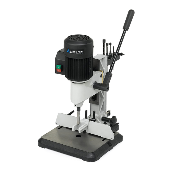
Delta Model 14-651 is easier to operate than a conventional drill press equipped with a mortising attachment. The model 14-651 is made of cast-iron and steel for rigidity and stability. The mortiser comes with a standard 3-jaw type chuck for positive gripping of mortising bits. - Page 6 HOLLOW CHISEL MORTISER PARTS Fig. 2 1. Mortising Machine 10. M6x1x25mm Pan Head Screws (2) (for assembling tool and chisel holder) 2. Tool and Chisel Holder 11. Spring 3. Chuck Key / Wrench 12. Bushing (for use with extra long chisels) 4.
- Page 7 ASSEMBLY FOR YOUR OWN SAFETY, DO NOT CONNECT THE MACHINE TO THE POWER SOURCE UNTIL THE MACHINE IS COMPLETELY ASSEMBLED AND YOU READ AND UNDERSTAND THE ENTIRE INSTRUCTION MANUAL. RAISING AND LOWERING HANDLE 1. Assemble hub of handle assembly (A) Fig. 3, to end of pinion shaft (B) and fasten handle to pinion shaft using special screw (C) and spring (D).
- Page 8 TOOL AND CHISEL HOLDER 1. Assemble tool and chisel holder (A) Fig. 7, to back of column using the two M6x1x25mm screws (B) and M6 lockwashers as shown. Fig. 7 2. Fig. 8, illustrates the chuck key/wrench (C), bushing (F) for use with extra long chisels, and chisels and bits (E) in holes of tool and chisel holder (A) when not in use.
- Page 9 2. Loosen screw (D) Fig. 11, and push chisel (B) up through hole in head as far as possible. Then lower chisel (B) 1/16" to 3/16" and tighten set screw (D). IMPORTANT: When inserting chisel (B) Fig. 12 into head, there must Fig.
- Page 10 5. The flat portion of the bit should be adjusted to a minimum of 1/16" below the bottom of the chisel, as shown in Fig. 15. For certain types of wood it may be necessary to increase this distance up to a maximum of 3/16"...
-
Page 11: Operating Controls And Adjustments
“OFF” position to prevent unauthorized use. This can be done by inserting the lockout pin (C) Fig. 21, Delta accessory model number 50-164, through the hole in the start button (A). Place the 1/8" shank of a lock through the hole in the lockout pin and secure the lock as shown. - Page 12 DEPTH STOP ROD A depth stop rod (A) Fig. 23, is provided to limit the depth of the chisel. To adjust the depth stop rod (A), loosen lever (C) and lower head until the chisel is at the desired depth. Lower depth stop rod (A) until it contacts the top of the column (D) and tighten lever (C).
- Page 13 CHISEL PARALLEL TO WORKPIECE The chisel (A) Fig. 26, can be adjusted parallel to the workpiece by loosening screw (B) and rotating chisel until the back surface of the chisel is touching workpiece. Then tighten screw (B). Fig. 26 SLIDING FIT BETWEEN HEAD AND COLUMN A dovetail gib (A) Fig.
- Page 14 ROTATING COLUMN 180 DEGREES The column (A) Fig. 31, can be rotated 180 degrees, as shown, if it is desired to cut workpieces off the table. To rotate the column, remove four screws, two of which are shown at (B), rotate column (A) 180 degrees and replace the four screws (B).
- Page 15 NOTES...
-
Page 16: Parts, Service Or Warranty Assistance
Two Year Limited Warranty Delta will repair or replace, at its expense and at its option, any Delta machine, machine part, or machine accessory which in normal use has proven to be defective in workmanship or material, provided that the customer returns the product prepaid to a Delta factory service center or authorized service station with proof of purchase of the product within two years and provides Delta with reasonable opportunity to verify the alleged defect by inspection. - Page 17 Delta Distributor, Authorized · Service Center, or Porter-Cable Delta Factory Service Center. If you do not have access to any of these, call 800-223-7278 and you will · be directed to the nearest Porter-Cable Delta Factory Service Center. Las Estaciones de Servicio Autorizadas están ubicadas en muchas grandes ciudades.
Need help?
Do you have a question about the 14-651 and is the answer not in the manual?
Questions and answers