Table of Contents
Advertisement
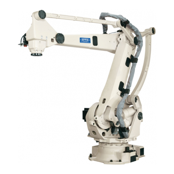
MANIPULATOR
INSTRUCTION MANUAL
LP-01 series [AX20/FD11]
・
Before attempting to operate the robot, please read through this operating manual
carefully, and comply with all the safety-related items and instructions in the text
・
The installation, operation and maintenance of this robot should be undertaken only
by those individuals who have attended one of our robot course
・When using this robot, observe the low related with industrial robot and with
safety issues in each country.
・
This operating manual must be given without fail to the individual who will be actually
.
operating the robot
・
Please direct any queries about parts of this operating manual which may not be
completely clear or any inquiries concerning the after-sale service of this robot to any
of the service centers listed on the back cover.
15th edition
2202, MLPEN-221-015,001
.
.
Advertisement
Table of Contents

Related Manuals for Nachi LP130-01


Summarization of Contents
Chapter 1 Basic Specifications
1.1 List of Basic Specifications
Provides a table detailing key specifications such as robot type, degrees of freedom, drive system, and load capacities.
1.2 Outline Dimensions and Motion Range
Illustrates the overall physical dimensions and operational movement range of the robot arms and axes.
1.3 Details of Load Mounting Face
Specifies the mounting interface details on the robot wrist for end effectors, including bolt patterns and depth.
1.4 Wiring and Piping Diagram for Application
Details the wiring and air piping connections for external applications on the robot's upper arm and base.
1.5 Operating Range Adjustment
Explains how to adjust the robot's operating range using mechanical and software limit stoppers for safety.
1.6 Coordinate Systems for Manual Operation
Describes the different coordinate systems (joint, tool, machine, user) available for robot manual operation.
1.7 Precautions for Tool Setting
Outlines important considerations and precautions when setting up tools, including TCP, weight, and inertia.
1.8 Brake Release Switch (Option)
Provides information on the optional brake release switch for manual movement of robot axes.
Robot Safety Precautions
Safety Tags and Marks Explanation
Explains the meaning of danger, warning, caution, and important tags used in the manual.
Manipulator Labels and Marks
Electrical Hazard Labels
Identifies labels related to electrical hazards and precautions for safe handling.
Hot Parts and Pinch Point Labels
Identifies labels for hot parts and pinch points on the manipulator to prevent burns and injuries.
Caution and Warning Labels
Details additional caution and warning labels for potential hazards during operation and maintenance.
Chapter 2 Precautions for Handling
2.1 Names of Robot Components
Identifies and labels the major parts and components of the robot arm.
2.2 Transport Procedure
Provides guidelines and safety measures for safely transporting the robot and its components.
2.3 Installation Procedure
Details the steps and safety considerations for installing the robot, including location and foundation requirements.
2.4 Allowable Load
Specifies the limits for payload, static load torque, and moment of inertia for the robot's wrist.
2.5 Performing Encoder Correction
Explains the procedure for correcting encoder data to ensure accurate robot positioning.
2.6 Emergency Stop During Transportation of Work-piece
Addresses potential damage to work-pieces during emergency stops while the robot is transporting them.
Chapter 3 Inspection
3.1 Inspection Items and Periods
Outlines the regular inspection schedule, items, and methods for maintaining robot performance.
3.2 Inspection of Major Bolts
Describes how to inspect and check the torque of major bolts on the robot's structure.
3.3 Inspection of Wrist
Details how to check the robot wrist for backlash and play by applying loads.
3.4 Inspection of Wirings
Provides inspection points for cables, tubes, and connectors on various parts of the robot.
3.5 Inspection of Grease
Explains how to inspect the grease for steel dust density and check lubrication points.
3.6 Inspection of Cooling Fan
Describes how to inspect the robot's cooling fan for proper operation and cleanliness.
Chapter 4 Maintenance
4.1 Lubrication
Provides guidelines for lubricating robot components, specifying grease type, amount, and frequency.
4.2 Grease Replacement
Details the procedure for replacing grease in the robot's reduction gears and support points.
4.3 Battery Replacement
Explains the procedure for replacing the backup batteries for encoder data.
Chapter 5 Troubleshooting
5.1 Probing into Causes of Troubles
Guides users on how to identify the cause of robot abnormalities by analyzing symptoms and defective parts.
5.2.1 Motor Replacement (J1,J2,J3 of LP130/180 and J1,J2 of LP210)
Step-by-step procedure for replacing motors on specific axes of the LP130/180 and LP210 robot models.
5.2.2 Motor Replacement (J2 of LP210)
Detailed procedure for replacing the motor on the J2 axis of the LP210 robot model.
5.2.3 Motor Replacement (J4)
Step-by-step guide for replacing the motor on the J4 axis of the robot.
5.2.4 Encoder Reset
Explains how to reset encoder data when it becomes corrupted or after motor replacement.
5.2.5 Encoder Correction
Details the procedure for correcting encoder values after reset or replacement to ensure proper positioning.
5.3 Encoder Replacement
Provides instructions on how to replace the encoder unit on robot axes.
Chapter 6 Recommended Spare Parts and Special Tools for Maintenance
Recommended Spare Parts
Lists recommended spare parts for periodical maintenance and general repairs, categorized by robot model.
Special Tools for Maintenance (Option)
Identifies optional tools required for efficient maintenance, such as zeroing pins and fixing jigs.
Chapter 7 Wiring Diagrams
Robot Parts Layout
Diagram showing the general layout of major robot components and connection panels.
Wiring/Piping Connection Diagram
Illustrates the wiring and piping connections between the controller and robot for older models.
Wire Connection Diagram for Motor and Brake (1)
Shows motor and brake wiring connections for older and newer robot models.
Wire Connection Diagram for Motor and Brake (2)
Depicts motor and brake wiring diagrams for specific robot models.
Wire Connection Diagram for Encoder (1)
Illustrates the wiring diagrams for encoder connections on axes J1, J2, and J3.
Wire Connection Diagram for Encoder (2)
Shows the wiring diagram for encoder connections on axis J4.
Wire Connection Diagram for Application
Diagram detailing the wiring for external application signals and hoses.
AX20 Controller Wire Harness Connection (1)
Details the wire harness connections for the AX20 controller, part 1.
AX20 Controller Wire Harness Connection (2)
Details the wire harness connections for the AX20 controller, part 2.
FD11 Controller Wire Harness Connection (1)
Illustrates wire harness connections for the FD11 controller, part 1.
FD11 Controller Wire Harness Connection (2)
Illustrates wire harness connections for the FD11 controller, part 2.
FD11 Controller Wire Harness Connection (3)
Illustrates wire harness connections for the FD11 controller, part 3.
Need help?
Do you have a question about the LP130-01 and is the answer not in the manual?
Questions and answers