Table of Contents
Advertisement
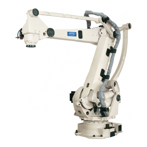
MANIPULATOR
INSTRUCTION MANUAL
LP-01 series [AX20/FD11]
・
Before attempting to operate the robot, please read through this operating manual
carefully, and comply with all the safety-related items and instructions in the text
・
The installation, operation and maintenance of this robot should be undertaken only
by those individuals who have attended one of our robot course
・When using this robot, observe the low related with industrial robot and with
safety issues in each country.
・
This operating manual must be given without fail to the individual who will be actually
.
operating the robot
・
Please direct any queries about parts of this operating manual which may not be
completely clear or any inquiries concerning the after-sale service of this robot to any
of the service centers listed on the back cover.
15th edition
2202, MLPEN-221-015,001
.
.
Advertisement
Table of Contents


Need help?
Do you have a question about the LP-01 Series and is the answer not in the manual?
Questions and answers