
Related Manuals for Nachi SRA220H Series


Summary of Contents for Nachi SRA220H Series
- Page 1 Standard specifications SRA220H-01-FD11 SRA220HV-01-FD11 7th edition 1707, SSRAEN-064-007,001...
-
Page 2: Table Of Contents
Table of contents 1. Outline........................1 2. Basic specifications....................2 3. Robot dimensions and working envelope..............3 4. Detail of load mounting plate..................5 5. Installation procedure ....................6 6. Allowable wrist load....................11 7. Option specifications ....................14 8. Application wiring and piping diagram ..............16 8.1 Spot welding specification 1 ................ -
Page 3: Outline
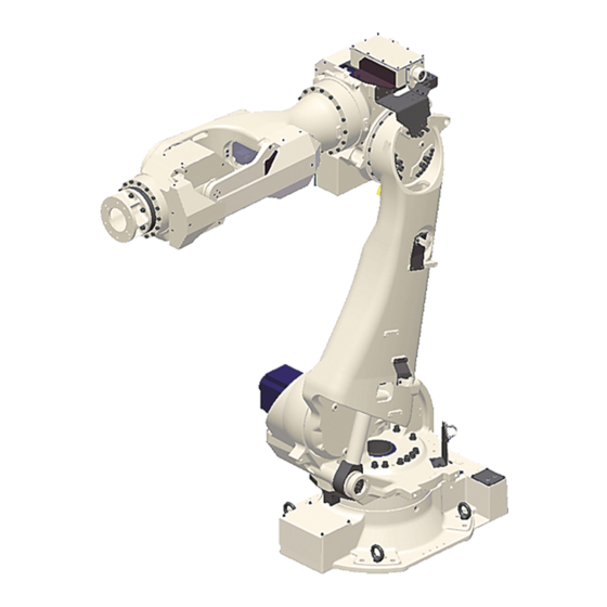
Page-1 1. Outline NACHI ROBOT “SRA220H” is optimal robot for spot welding, material handling and other applications, and provides dramatically improved productivity by its overwhelming speed and compact body. Floor mount and inverted mount type is prepared. Standard type Installation Max. -
Page 4: Basic Specifications
Page-2 2. Basic specifications Item Specifications Robot model SRA220H-01 SRA220HV-01 Construction Articulated Number of axis Drive system AC servo motor ±2.88 rad(±165°) Axis 1 ±3.14 rad(±180°) -1.40 ~ +1.05rad(-80 ~ +60°) Axis 2 -2.69 ~ +2.62rad(-154~+150°) Axis 3 Max. working envelope Axis 4 ±3.66 rad(±210°)... -
Page 5: Robot Dimensions And Working Envelope
Page-3 3. Robot dimensions and working envelope 【SRA220H-01】... - Page 6 Page-4 【SRA220HV-01】...
-
Page 7: Detail Of Load Mounting Plate
For the end effecter fixing bolts, use the mounting P.C.D. shown in the following figures. Another P.C.D. is prepared as option. Consult with each NACHI-FUJIKOSHI office for the details. Be sure to screw the M10 tool fixing bolts in the wrist not deeper than the screw depth in the mounting face. -
Page 8: Installation Procedure
Page-6 5. Installation procedure The installation location and the installation procedure of the robot are critical factors to maintain robot functions. The ambient conditions of installation location not only have influence on the life of mechanical sections of the robot, but also get involved in safety issues. Consequently, strictly observe the environmental conditions shown below. - Page 9 Page-7 ■ Installation procedure While robot moves, large reaction force is applied to the swiveling base from all directions. Consequently, the robot should be installed in such a manner that the foundation endures not only the static loads but also the reaction force caused by robot movement. 【SRA220H-01】...
- Page 10 Page-8 ■ Installation space To install the robot, lock the swiveling base of the robot. The mechanical stopper end is located in a position exceeding the specified working envelope (software limit) of axis 1 by 3°. To install the safety fence, with consideration WARNING given to the wrist configuration and the shape of end effecter.
- Page 11 Page-9 【SRA220HV-01】 Robot type...
- Page 12 Page-10 ■ Accuracy of installation surface When installing robot, strictly observe precautions listed below to cause no deformation in the swivel base. (1) Make the deviation from the flatness of the 4 plates on the robot installation surface fall within 1.0 mm. (2) Make the deviation in height between the 4 places of each base plate installation surface and the robot installation surface fall in the range of 1.0 mm (±0.5 mm).
-
Page 13: Allowable Wrist Load
Page-11 6. Allowable wrist load Load fixed on the tip of wrist is regulated by “allowable payload mass”, “allowable static load torque”, and “allowable moment of inertia”. Strictly keep the wrist load within each allowable value. If wrist load exceeds the allowable value, this robot is out of guarantee. Refer to the table of “2. - Page 14 Page-12 ■ How to find the inertia moment of each axis Point A coordinate system Origin is Point A (intersection point of axis 6 , 4 rotation center and axis 5 rotation center) and its X, Y and Z direction are d efined as X: Perpendicular coordinate with Y, Z Y: Axis 5 rotation cen te r when wrist is in reference position Z: Axis 6 and 4 rotation cen te r when wrist is in reference position...
- Page 15 Page-13 ■ Allowable forearm load Use the robot under condition that COG of the ancillary equipment on the forearm falls in the range shown below. 【SRA220H-01】 【SRA220HV-01】 When wrist load is 220kg 【SRA220H-01】 【SRA220HV-01】 When wrist load is 190kg...
-
Page 16: Option Specifications
Page-14 7. Option specifications ○: Possible to correspond/-: Impossible to correspond Robot model Item Specifications Parts No. ○ Chemical anchor specification with pin hole OP-F1-024 ○ Base plate welded (anchors not included) without pin hole OP-F1-028 ○ with pin hole Hammer drive anchor specification OP-F2-018 ○... - Page 17 Page-15 ■Motion range limit option table (Please select the option part number to order referring to the following table.) Function Axis name ● - Axis 1 Without Only adjustable - ● Axis 2 stopper - ● Axis 3 Motion range Axis 1・2・3 ●...
-
Page 18: Application Wiring And Piping Diagram
8. Application wiring and piping diagram Application wiring and piping written here is the best designed specification for spot welding usage. No free space is remained in hollow space. If another specification is required, please contact to NACHI-FUJIKOSHI office. Spot welding specification 1 Standard... - Page 19 Page-17 Tool side wiring specification Name Item Specification Edge manufacturing ・Welding cable 38mm (single wire) x3 No manufacturing ・Signal cable 0.2mm x20 wires No manufacturing ・D-ET cable No manufacturing Cable ・ETHERNET cable No manufacturing ・Servo gun cable (power) x1 Connector type:MS3106A20-17S(190) Spot welding ・Servo gun cable (signal) x1 Connector type:MS3106A20-29S(190)
-
Page 20: Spot Welding Specification 2
Page-18 Spot welding specification 2 Standard Connecting diagram... - Page 21 Page-19 Tool side wiring specification Name Item Specification Edge manufacturing ・Welding cable 22mm (single wire) x3 3-M8 terminal ・Signal cable 0.2mm x20 wires No manufacturing Cable ・Servo gun cable (power) x1 Connector type:MS3106A20-17S(190) Spot welding ・Servo gun cable (signal) x1 Connector type:MS3106A20-29S(190) specification ・Water inlet tube:Green(*1,*2)...
-
Page 22: Safety Measures Against Transport
Gas in balancer must be released when robot is transported by air. Gas in balancer must be charged before using robot, so customer needs to prepare the nitrogen gas and charging unit. Please contact to NACHI-FUJIKOSHI office to order the WARNING charging unit. - Page 23 Page-21 Never use taps marked ※ to hang the robot. (4-M20) Hanging bolt installation hole (4-M20) If hanging wires push the encoder connectors or wiring/piping, they may be broken when hanging the robot. When hanging the robot, please pay attention not to make the wires touch the encoder connectors and wiring/piping.
-
Page 24: Delivery Style (Specification Which Contains A Robot)
2. Operation and maintenance education The special spot operation guide and the special spot preservation guide are the outside of the estimation. Consult with each NACHI-FUJIKOSHI office for the details as for the schooling system. 11. Consuming power (Robot + Controller) 7.0 kVA (may vary according to the application and motion pattern.) - Page 26 Phone +81-76-423-5137 +81-76-493-5252 NACHI-FUJIKOSHI CORP. holds all rights of this document. No part of this manual may be photocopied or reproduced in any from without prior written consent from NACHI-FUJIKOSHI CORP. Contents of this document may be modified without notice. Any missing page or erratic pagination in this document will be replaced.
Need help?
Do you have a question about the SRA220H Series and is the answer not in the manual?
Questions and answers