Advertisement
Table of Contents
- 1 Table of Contents
- 2 Outline
- 3 Basic Specifications
- 4 Robot Dimensions and Working Envelope
- 5 Detail of Load Mounting Plate
- 6 Installation Procedure
- 7 Allowable Wrist Load
- 8 Option Specifications
- 9 Application Wiring and Piping Diagram
- 10 Safety Measures against Transport
- 11 Delivery Style (Specification Which Contains a Robot)
- 12 Consuming Power (Robot + Controller)
- 13 Paint Color
- 14 Warranty
- Download this manual
Advertisement
Table of Contents

Related Manuals for Nachi SRA-H Series


Summary of Contents for Nachi SRA-H Series
- Page 1 Standard specifications SRA-H-01-FD11 SRA-HL-01-FD11 6th edition 1608, SSRAEN-071-006,001...
-
Page 2: Table Of Contents
Table of contents 1. Outline........................1 2. Basic specifications....................2 3. Robot dimensions and working envelope..............3 4. Detail of load mounting plate..................6 5. Installation procedure ....................8 6. Allowable wrist load....................11 7. Option specifications ....................18 8. Application wiring and piping diagram ..............21 9. -
Page 3: Outline
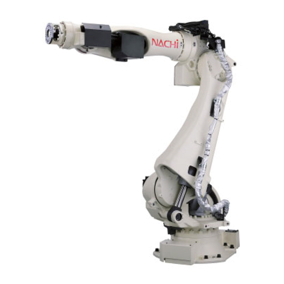
Page-1 1. Outline NACHI ROBOT “SRA-H series” is optimal robot for spot welding, material handling and other applications, and provides dramatically improved productivity by its overwhelming speed and compact body. This series contains not only the “Standard type” but also the “Long arm type” which spreads its... -
Page 4: Basic Specifications
Page-2 2. Basic specifications Item Specifications Robot model SRA100H-01 SRA133H-01 SRA166H-01 SRA210H-01 SRA133HL-01 Construction Articulated Number of axis Drive system AC servo motor Axis 1 ±3.14 rad(±180°) -1.40 ~ +1.05 rad(-80 ~ +60°) Axis 2 -2.56 ~ +2.62 rad -2.33 ~ +2.62 rad Axis 3 Max. -
Page 5: Robot Dimensions And Working Envelope
Page-3 3. Robot dimensions and working envelope 【SRA100H-01】 【SRA133H-01】... - Page 6 Page-4 【SRA166H-01】 【SRA210H-01】...
- Page 7 Page-5 【SRA133HL-01】...
-
Page 8: Detail Of Load Mounting Plate
For the end effecter fixing bolts, use the mounting P.C.D. shown in the following figures. Another P.C.D. is prepared as option. Consult with each NACHI-FUJIKOSHI office for the details Be sure to screw the M10 tool fixing bolts in the wrist not deeper than the screw depth in the mounting face. - Page 9 Page-7 ■ Upper part of forearm Ancillary equipment can be mounted to the upper part of robot forearm. 【SRA100H-01】【SRA133H-01】【SRA166H-01】【SRA210H-01】【SRA133HL-01】 Bracket Gear box Cross section view of Z-Z (4 portions)
-
Page 10: Installation Procedure
Page-8 5. Installation procedure The installation location and the installation procedure of the robot are critical factors to maintain robot functions. The ambient conditions of installation location not only have influence on the life of mechanical sections of the robot, but also get involved in safety issues. Consequently, strictly observe the environmental conditions shown below. - Page 11 Page-9 ■ Installation space To install the robot, lock the swiveling base of the robot. The mechanical stopper end is located in a position exceeding the specified working envelope (software limit) of axis 1 by 3°. To install the safety fence, with consideration given to the wrist configuration and the shape of end effecter.
- Page 12 Page-10 ■ Accuracy of installation surface When installing robot, strictly observe precautions listed below to cause no deformation in the swivel base. (1) Make the deviation from the flatness of the 4 plates on the robot installation surface fall within 1.0 mm. (2) Make the deviation in height between the 4 places of each base plate installation surface and the robot installation surface fall in the range of 1.0 mm (±0.5 mm).
-
Page 13: Allowable Wrist Load
Page-11 6. Allowable wrist load Load fixed on the tip of wrist is regulated by “allowable payload mass”, “allowable static load torque”, and “allowable moment of inertia”. Strictly keep the wrist load within each allowable value. If wrist load exceeds the allowable value, this robot is out of guarantee. Refer to the table of “2. - Page 14 Page-12 [SRA166H-01] [SRA210H-01]...
- Page 15 Page-13 ■ Wrist load conditions Static load torque and moment of inertia of wrist load should exist inside the range shown below. If the real inertia is over the limit written in “2. Basic specifications”, maximum speed will IMPORTANT be restrained by software. [SRA100H-01] Axis 4, 5 Axis 6...
- Page 16 Page-14 Axis 4, 5 [SRA166H-01] Axis 6 Axis 4, 5 [SRA210H-01] Axis 6...
- Page 17 Page-15 ■ How to find the inertia moment Wrist coordinate system X: Perpendicular coordinate wit h Y, Z Y: Axis 5 rotation cen te r when wrist is in reference position Z: Axis 6 and 4 rotation cen te r when wrist is in reference position Tool COG coordinate system (Orig in is C O G o f to ol, an d p aralle l t o w rist co ord in at e sys tem ) x: Parallel t o X...
- Page 18 Page-16 ■ Allowable forearm load Use the robot under condition that COG of the ancillary equipment on the forearm falls in the range shown below. 【SRA100H-01】 When wrist load is 100kg 【SRA133H-01】 When wrist load is 133kg 【SRA166H-01】 When wrist load is 166kg 【SRA210H-01】...
- Page 19 Page-17 【SRA133HL-01】 When wrist load is 133kg...
-
Page 20: Option Specifications
Page-18 7. Option specifications ○: Possible to correspond/-: Impossible to correspond Robot model Item Specifications Parts No. ○ ○ ○ ○ ○ Chemical anchor specification with pin hole OP-F1-024 ○ ○ ○ ○ ○ Base plate welded (anchors not included) without pin hole OP-F1-028 ○... - Page 21 Page-19 ■ Motion range limit option table (Please select the option part number to order referring to the following table.) Function Axis name ● - Axis 1 Without Only adjustable - ● Axis 2 stopper - ● Axis 3 Motion range Axis 1・2・3 ●...
- Page 22 Page-20 ■ Extension flange tool mounting face Cables and tubes are pulled out from the side. Applicable for P.C.D.92/P.C.D.125 and P.C.D.160. Two type is prepared for attachment phase of P.C.D.92/P.C.D.125. Attachment phase of P.C.D.160 is same for both flanges. (Pin arrangement is direction of P.C.D.92/P.C.D.125 pins when axis 6 is in 0 degree) Tool mounting face of OP-W3-013 (Pin arrangement is vertical) Tool mounting face of OP-W3-014 (Pin arrangement is horizontal)
-
Page 23: Application Wiring And Piping Diagram
8. Application wiring and piping diagram Application wiring and piping written here is the best designed specification for spot welding usage. No free space is remained in hollow space. If another specification is required, please contact to NACHI-FUJIKOSHI office. ■ Spot welding specification Standard... - Page 24 Page-22 Tool side wiring specification Edge manufacturing Cable Length from end effecter mounting face Name Item Specification diameter 1.5m (SRA100H,133H,166H,210H) (mm) 1.2m (SRA133HL) ・ Welding cable 22 mm (single wire) x3 (Piping of axis 1 ; 3-M8 terminal (R22-8S) 12.9~13.5 Without seal connector 22 mm ×2...
- Page 25 Page-23 ■ Detailed diagram of the application connectors BJ1 side (connector) (option) User-side Connectors Wire-side shell: JFM-WSA-4-A (JST) or JFM-WSA-4-C (JST) Guide plate A kit: JFM-GPAK-4 (JST) Receptacle housing: JFM2FDN-22V-K (JST) Receptacle contact: a: SJ2F-01GF-P1.0 (JST) (0.20 ∼ 0.50 mm b: SJ2F-21GF-P1.0 (JST) (0.30 ∼...
-
Page 26: Safety Measures Against Transport
Page-24 9. Safety measures against transport The robot must be transported by personnel who have licenses required for slinging work, crane operation, forklift truck operation, and others. The weight of the robot and controller is listed in the Operating Manual and the Maintenance Manual. Check for the WARNING weight, and then handle them according to procedures suitable for the weight. - Page 27 Page-25 If hanging wires push the encoder connectors or wiring/piping, they may be broken when hanging the robot. When hanging the robot, please pay attention not to make the wires touch the encoder connectors and wiring/piping. CAUTION...
-
Page 28: Delivery Style (Specification Which Contains A Robot)
2. Operation and maintenance education The special spot operation guide and the special spot preservation guide are the outside of the estimation. Consult with each NACHI-FUJIKOSHI office for the details as for the schooling system. 11. Consuming power (Robot + Controller) 7.0 kVA (may vary according to the application and motion pattern.) - Page 30 Phone +81-76-423-5137 +81-76-493-5252 NACHI-FUJIKOSHI CORP. holds all rights of this document. No part of this manual may be photocopied or reproduced in any from without prior written consent from NACHI-FUJIKOSHI CORP. Contents of this document may be modified without notice. Any missing page or erratic pagination in this document will be replaced.
Need help?
Do you have a question about the SRA-H Series and is the answer not in the manual?
Questions and answers