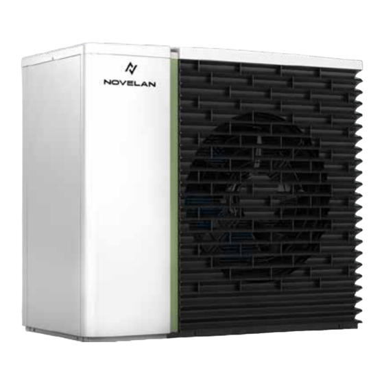
Summarization of Contents
About this Operation Manual
Validity
Manual applies only to the unit identified by the nameplate.
Reference Documents
Lists additional documents providing information to this manual.
Symbols and Markings
Explains warnings, symbols, and their meanings used in the document.
Contact Information
Provides addresses for purchasing accessories, service, and general inquiries.
Safety
Proper Use
Defines intended use, operating conditions, and local regulations.
Personnel Qualifications
Specifies required qualifications for operating and working on the unit.
Personal Protective Equipment
Lists necessary protective gear for safe operation and maintenance.
Residual Risks
Details risks from electric current, high temperatures, and moving parts.
Disposal
Instructions for environmentally safe disposal of hazardous substances.
Avoid Material Damage
Lists substances to avoid in ambient air to prevent unit damage.
Description
Condition on Delivery
Describes how the unit is delivered.
Design
Illustrates and labels the main components of the unit.
Functionally Necessary Accessories
Lists essential accessories required for proper unit operation.
Additional Accessories
Lists optional accessories available for the unit.
Function
Explains the working principle of the heat pump and cooling function.
Operation and Care
Energy and Environmentally Aware Operation
Provides measures for efficient and eco-friendly operation.
Care
Instructions on how to clean and maintain the unit's exterior.
Delivery, Storage, Transport and Installation
Scope of Delivery
Lists items included in the unit's delivery package.
Storage
Guidelines for storing the unit safely and protected.
Unpacking and Transport
Instructions for safely unpacking and transporting the heat pump unit.
Installation
Details site requirements, clearances, and mounting options for installation.
Opening and Closing the Unit
Steps for accessing internal components by opening and closing the unit cover.
Installation of Hydraulic System
Condensate Drain
Instructions for connecting and installing the condensate drain pipe.
Connection to the Heating Circuit
Guides on connecting the unit to the existing heating circuit safely.
Pressure Safety
Requirements for ensuring pressure safety in the heating circuit.
Electrical Installation
Establishing the Electrical Connections
Details on making safe and compliant electrical connections to the unit.
Mounting EVS 8 / EVS Accessories
Step-by-step guide for mounting the EVS 8 / EVS accessory.
Flushing, Filling and Venting
Heating Water Quality
Specifies requirements for heating water quality to prevent system damage.
Flushing, Filling and Venting the Heating Circuit
Procedures for flushing, filling, and venting the heating circuit.
Commissioning
Commissioning Checklist
Checklist and procedures for safe and correct commissioning of the unit.
Maintenance
Basic Principles
General principles for heat pump maintenance and local regulations.
Maintenance After Commissioning
Checks and cleaning procedures to be performed after initial commissioning.
Maintenance As Required
Regular checks and cleaning of components for ongoing maintenance.
Cleaning and Flushing the Condenser
Steps for cleaning and flushing the heat pump's condenser.
Annual Maintenance
Annual checks and water quality analysis for optimal system performance.
Malfunctions
Malfunction Identification
Guidance on identifying and troubleshooting unit malfunctions using diagnostic programs.
Dismantling and Disposal
Dismantling
Procedures and safety precautions for dismantling the unit.
Disposal and Recycling
Guidelines for environmentally responsible disposal and recycling of unit components.
Technical Data and Scope of Supply
Performance Data
Detailed performance specifications for heating and cooling capacities.
Operating Limits
Defines the operational boundaries and temperature ranges for the unit.
Sound
Specifies sound power levels measured under various conditions.
Performance Curves
Helox 11 Heating Mode
Graphs illustrating performance characteristics in heating mode.
Helox 11 Cooling Mode
Graphs showing performance data for the unit in cooling mode.
Helox 16 Heating Mode
Graphs detailing performance characteristics in heating mode.
Helox 16 Cooling Mode
Graphs illustrating performance data for the unit in cooling mode.
Installation Variants
Floor Bracket with Wall Duct
Illustrates installation variant using a floor bracket and wall duct.
Floor Bracket with Hydraulic Connection Line
Illustrates installation variant with floor bracket and hydraulic connection.
Direct Foundation with Hydraulic Connection Line
Illustrates installation variant directly on foundation with hydraulic connection.
Keys for Diagrams and Plans
Dimensional Drawings / Installation Plans
Explains symbols and their meanings for diagrams and installation plans.
Parallel Mode
Basic Information
Introduces parallel mode, connection requirements, and buffer tank volumes.
Sound Level Increase
Explains how sound levels increase and how to calculate it.
Protection Zones and Safety Distances
Defines safety zones and distances required for parallel installations.
Clearance for Servicing
Specifies required clearances for servicing heat pumps in parallel mode.
Minimum Clearances
Details essential minimum clearances for parallel heat pump installations.
Installation Variants
Describes different installation arrangements for parallel mode.
Condensate Line Connection
External Connection
Provides instructions for connecting the condensate line externally.
Internal Connection
Provides instructions for connecting the condensate line internally.
Coastal Installation
Installation Guidelines
Guidelines for installing the unit in coastal environments.
Hydraulic Integration Examples
With Hydraulic Tower
Example schematic for hydraulic integration with a hydraulic tower.
With Hydraulic Module
Example schematic for hydraulic integration with a hydraulic module.
With Wall-Mounted Controller
Example schematic for hydraulic integration with a wall-mounted controller.
Diagram Keys
General
Lists all symbols used in diagrams and their meanings.
Circuit Diagrams
1/5
First part of the electrical circuit diagram for the unit.
2/5
Second part of the electrical circuit diagram for the unit.
3/5
Third part of the electrical circuit diagram for the unit.
4/5
Fourth part of the electrical circuit diagram for the unit.
5/5
Fifth part of the electrical circuit diagram for the unit.


Need help?
Do you have a question about the HELOX 16 and is the answer not in the manual?
Questions and answers