Table of Contents
Advertisement
Quick Links
Advertisement
Table of Contents

Related Manuals for Novelan LAP Series


Summary of Contents for Novelan LAP Series
- Page 1 Operating Manual Air/Water Heat Pumps Outdoor installation 83059703kUK...
-
Page 2: Table Of Contents
Table of contents 12 Maintenance About this operating manual ..........17 ...... 3 12.1 Basic principles ........17 Validity ............3 12.2 Maintenance after commissioning ..17 Other applicable documents ..... 3 12.3 Maintenance as required ......18 Symbols and markings ......3 ..... -
Page 3: About This Operating Manual
About this operating manual Symbol Meaning Safety-relevant information. This operating manual is part of the device. Warning of physical injuries. Danger of fatal injury due to Before working on or with the device, read the electric current. operating manual carefully and follow it for all DANGER Indicates an imminent danger re- activities at all times, especially the warnings and... -
Page 4: Contact
Interference and are kept up-to-date: DE: www.novelan.com injuries and damage to property. AT: www.novelan.at Ensure that personnel are familiar with local regulations, especially those on safe and hazard- aware working. -
Page 5: Disposal
Injuries caused by moving parts 2.6 Avoid damage to property Only switch on the unit once outer panels and fan The ambient air at the heat pump installation site, as well as the air drawn in as a heat source, must not contain any corrosive constituents! Injuries due to high temperatures Constituents such as... -
Page 6: Description
If a system is not planned, designed, started up and Description operated in accordance with the given requirements, there is a risk that the following damage and faults will 3.1 Delivery condition occur: Malfunctions and the failure of components, e.g. pumps, valves Internal and external leaks, e.g. -
Page 7: Layout
3.2 Layout 3.3 Accessories The following accessories are available for the device NOTE through the manufacturer's local partner: This section essentially names Domestic hot water tank described in this operating manual. Air / magnetic sludge separator Room thermostat to switch the cooling function Dew point monitor to protect a system with cooling Recirculating pumps Switching valves... -
Page 8: Operation And Care
Cooling Delivery, storage, transport and installation Cooling is integrated in the units. The following options are possible for units with cooling function operating manual for the heating and heat pump controller): IMPORTANT Damage to the housing and the device components Active cooling due to heavy objects. -
Page 9: Installation
The hydraulic connections are not designed for The slings must be attached so that the device mechanical loads. cannot tilt! Lift the unit with the crane and place it on the Do not lift or transport the device by the hydraulic base. - Page 10 Installation Carefully lift the water protection barriers out of the interior of the unit. Do not damage any com- ponents when lifting out. CAUTION In the air outlet area, the air temperature is approx. 5 K below the ambient temperature. Under certain climatic conditions, an ice layer can therefore form in the air outlet area.
-
Page 11: Hydraulic Installation
After correct placement on the ventilator ring Hydraulic installation plates ( ), 8 screw threads ( ) protrude from each water protection barrier ( ). IMPORTANT Components and lines for desuperheating must be able to withstand temperatures up to 90°C. IMPORTANT Avoid open heating systems and / or heating systems Use the mounting material from the accessory... - Page 12 Make sure that the working overpressure is com- plied with. circuit via vibration decouplers. You must install them to prevent the transfer of structurally borne “Technical data / scope of supply", page 20). Install the outside pipes of the heating circuit be- neath the frost line.
-
Page 13: Vertical Connection
6.1 Vertical connection 6.2 Horizonzal connection View from below: View from inside: Open break-outs on the right sidewall Trim the 4 hoses (accessories) to length if required. Likewise the condensate hose inside the unit, which hangs loose from the condensate pan. Attach the hoses and the condensation hose and lead out on the right side. -
Page 14: Electrical Installation
Electrical installation Connect cables to the respective terminals ( “Terminal diagrams", from page 34). Connect the electrical cables IMPORTANT Irreparable damage to the compressor due to wrong the compressor load infeed. Basic information about the electrical connection companies may apply to electrical connections Fit the power supply for the heat pump with an 1 Feed-through glands all-pole circuit breaker with at least 3 mm contact... -
Page 15: Heating Water Quality
In the case of on-site circulating pumps, the deliv- ery rate is reduced; in the case of integrated cir- 8.1 Heating water quality The compatibility of the material of the compo- nents used with the antifreeze mixture must be ensured NOTE For detailed information refer, among other things, to the VDI Guidelines 2035 “Vermei-... -
Page 16: Insulate Hydraulic Connections
Insulate hydraulic connections Insulate hydraulic lines in accordance with local NOTE regulations. The activities in this section are only necessary for the integration of storage Perform a pressure test and check for leaks. tanks in series . Complete the work steps quickly, otherwise Insulate external piping on site. -
Page 17: Commissioning
11 Commissioning 12 Maintenance CAUTION NOTE Prior to commissioning the unit, the fan recommend that conclude protection grilles must be mounted and maintenance agreement with an accredited the facing panels closed. heating company. The relevant planning and design data of the sys- NOTE tem is documented in full Water accumulations resulting from extreme... -
Page 18: Maintenance As Required
Check at regular intervals whether the evaporator and the leaf guard need to be cleaned 1 Evaporator (left, right) 2 Leaf guard Unscrew both top sidewalls for best possible access. If necessary remove leaves and contaminants. Reattach sidewalls. Check at regular intervals that the condensate can drain out of the device freely, without ob- struction. -
Page 19: Yearly Maintenance
12.5 Yearly maintenance 14 Dismantling and disposal Record the quality of the heating water analytically. 14.1 Dismantling suitable measures without delay. Collect all media safely. Check all installed dirt traps for dirt and clean Separate components by their materials. them if necessary. 14.2 Disposal and recycling Dispose of environmentally hazardous media 13 Malfunctions... -
Page 20: Technical Data / Scope Of Supply
Technical data / scope of supply Performance data Values in brackets: (1 Compressor) LAP45AR3 Heating capacity | COP for A7/W35 acc. to DIN EN 14511-x kW | COP 47.8 (31.03) | 3.57 (4.58) for A7/W45 acc. to DIN EN 14511-x kW | COP —... -
Page 21: Performance Curves
Performance curves / operating limits / heating LAP 45AR3 Qh (kW) Temp„ (°C) Pe (kW) 35°C 1VD 55°C 1VD 35°C 2VD 55°C 2VD Temp„ (°C) Temp„ (°C) ∆p (bar) ∆p (bar) 1,500 0,125 1,350 1,200 0,100 1,050 0,900 0,075 0,750 0,600 0,050 0,450... - Page 22 LAP 45AR3 Performance curves / operating limits / cooling Q0 (kW) Temp¤ (°C) Pe (kW) 7°C 1VD 18°C 1VD 10°C 2VD 18°C 2VD Temp¤ (°C) Temp¤ (°C) ∆p (bar) ∆p (bar) 0,125 1,500 1,350 0,100 1,200 1,050 0,075 0,900 0,750 0,050 0,600 0,450...
- Page 23 Performance curves / Heißgasnutzung LAP 45AR3 Hz A2 Hz A7 35°C 2VD 35°C 1VD 55°C 2VD 55°C 1VD Temp (°C) Temp (°C) Kh A27 Hz A-7 35°C 2VD 7°C 1VD 55°C 2VD Temp (°C) Temp (°C) ∆p (bar) Kh A35 0,125 0,100 18°C 2VD...
-
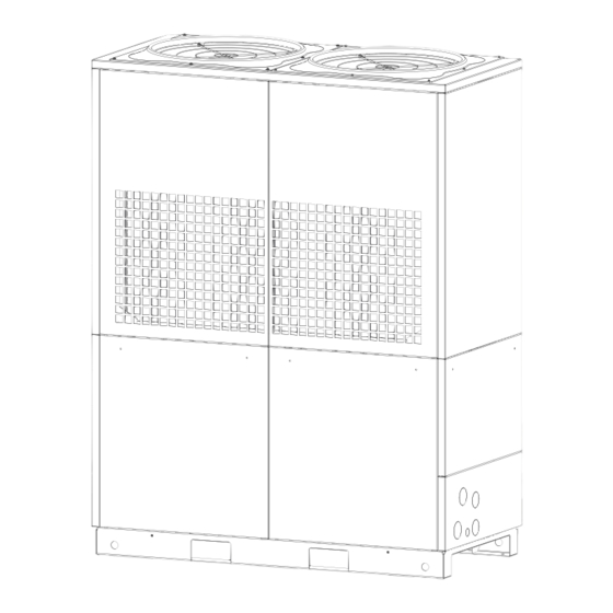
Page 24: Dimensional Drawings
LAP 45AR3 Dimensional drawings Keys: 819491b All dimensions in mm. Pos. Name Pos. Name Horizontal connection area: water + condensate Cut A-A Vertical connection area: water + condensate + Rear view feed-through electrical connections Side view from the right Control cabinet Plan view Main switch Facing panel...
Need help?
Do you have a question about the LAP Series and is the answer not in the manual?
Questions and answers