
Related Manuals for Novelan LIV Series


Summary of Contents for Novelan LIV Series
- Page 1 Operating Manual Air/Water Heat Pumps Indoor installation LIV – series 83059103jUK...
-
Page 2: Table Of Contents
Table of contents 13 Faults About this operating manual .............. 20 ...... 3 Validity ............3 14 Dismantling and disposal ......20 Reference documents ....... 3 14.1 Dismantling ..........20 Symbols and markings ......3 14.2 Disposal and recycling ......20 Contact ............ -
Page 3: About This Operating Manual
About this operating manual 1.3 Symbols and markings This operating manual is part of the unit. Identification of warnings Before working on or with the unit read the Symbol Meaning operating manual carefully and follow it for all Safety-relevant information. activities at all times, especially the warnings and Warning of physical injuries. -
Page 4: Contact
DE: www.novelan.com Ensure that the personnel is familiar with the local AT: www.novelan.at regulations, especially those on safe and hazard- aware working. -
Page 5: Disposal
Injury due to moving parts Improper action Switch device on only with air ducts and weather Requirements for minimum scale and corrosion and/or rain protection grid fitted. damage in hot water heating systems: Proper planning, design and commissioning Injuries and environmental damage due to Closed system with regard to corrosion refrigerant Integration... -
Page 6: Description
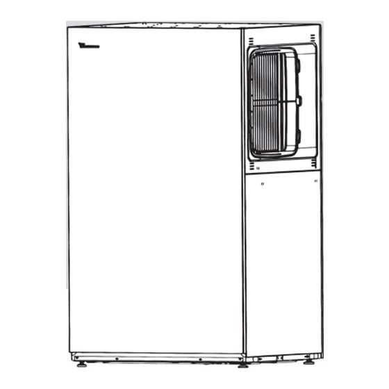
Description The heat pump module 3.1 Delivery condition 1 Evaporator module 2 Fan module 3 Fan 4 Refrigerant circuit module The refrigerant circuit module 1 Blind cover and louvre grille 2 Side wall (2-piece) and cover 3 Rear wall 4 Side wall (complete) 5 Front wall 6 Supporting crosspiece (left and right;... -
Page 7: Accessories
Nameplates The integrated vibration decouplers for the hydraulics prevent structure-borne sound and vibrations from One nameplate is attached to the heat pump module in being transferred into the fixed pipes and therefore the rear facade cut-out at the factory. into the building. Two further nameplates are included in the delivery. -
Page 8: Care
4.2 Care 5.2 Storage Wipe down the outside of the unit only using a damp Do not unpack the unit until directly before cloth or cloth with mild cleaning agent (washing-up installation if possible. liquid, neutral cleaning agent). Do not use any harsh, Store unit protected against abrasive, acid or chlorine-based cleaning agents. - Page 9 The façade front is located in front of the device Carrying the unit and transporting with a handcart The single-part and two-part side wall are located on the rear side Housing walls are set down. There are two lashing straps around the heat pump Optional disconnection of the fan module module with grip openings at different heights.
-
Page 10: Installation
5.4 Installation NOTE The noise emissions of the heat pumps CAUTION must be taken into account in the respective In the air outlet area the air temperature is installation plans for air/water heat pumps. approx. 5 K below the ambient temperature. The respective regional regulations must be Under certain climatic conditions, an ice observed. -
Page 11: Installation Of Air Ducting
Open the strap tensioner and turn the hook on the 5.5 Installation of air ducting base plate through 90°. Air discharge to right or left Left air outlet Right air outlet 90° Attach the swelling tape to the louvre grille and blind cover by applying it around the edges and then sticking it in place. -
Page 12: Installation Of Hydraulic System
Installation of hydraulic system 1 Heating water supply 2 Condensate nozzle 3 Heating water return IMPORTANT Insert the vent at the highest point of the heating Dirt and deposits in the (existing) hydraulic system circuit. can cause damage to the heat pump. Ensure that working... -
Page 13: Electrical Installation
Electrical installation Guide the load cable and bus cable in a cable con- duit from the heat pump module up to the building feed-through, and from there to the wall-mounted Connect the electrical cables controller or the hydraulic unit inside the building. Connect the compressor load cable to the five-pin IMPORTANT plug included in the scope of delivery of the heat... - Page 14 With a three-wire load line (230 V compressor at Insert the PE conductor and L conductor 8 kW device), insert the N and PE conductor in in the same way in the corresponding plug the plug pins labelled accordingly and insert the L pins labelled on the plug: conductor in the L1 plug pin.
- Page 15 2.10. Screw the strain relief screw tight. 3.4. Pull back the shielding foil up to the shielding braid and cut off. 3.5. Strip each wire 9 mm. Connect the bus cable (communication) to the bus plug included in the scope of delivery of the heat pump.
- Page 16 3.9. Pull the operating tool or screwdriver out of the Connect the contact spring and bus cable (com- bus plug and thereby lock the connection of plug munication) in the same way to the five-pin bus connector socket included in the scope of deliv- ery of the heat pump and assemble the connector socket housing.
-
Page 17: Flushing, Filling And Venting
Flushing, filling and venting Pull the U-clip off the floor of the valve motor. Pull the valve motor carefully off the 3-way switch- ing valve. 8.1 Heating water quality Vent system at the respective highest point. Vent heat pump. NOTE For detailed information refer, among other things, to the VDI Guidelines 2035... -
Page 18: Set The Overflow Valve
10 Set the overflow valve The “Set bypass valve” menu item is set by default to “No”. The overflow valve adjustment function is deac- tivated. The UWP control signal is the indication of the NOTE currently required pump capacity in % The activities in this section are only necessary for the integration of storage If the flow rate is the current flow rate (measuring... -
Page 19: Commissioning
11 Commissioning 12 Maintenance CAUTION NOTE The unit may only be started up if the air recommend that conclude ducts, weather and/or rain louvres have maintenance agreement with an accredited been installed and the facing panels are heating company. closed. 12.1 Basic principles Relevant planning &... -
Page 20: Clean And Flush Condenser
Check evaporator and condensate pan 12.3 Clean and flush condenser and clean if required Clean and flush the condenser in accordance with Remove the front panel and the cover, thus gain- the manufacturer's instructions. ing access to the cleaning opening After flushing the condenser with chemical cleaning product: neutralise any residues and flush the condenser thoroughly with water. -
Page 21: Technical Data / Scope Of Supply
Technical data / Scope of supply Performance data Values in brackets: (1 Compressor) LIV 8.2R1/3 LIV 12.2R3 Heating capacity | COP for A10/W35 acc. to DIN EN 14511-x: 2013 Partial load operation kW | COP for A7/W35 acc. to DIN EN 14511-x: 2013 Partial load operation kW | COP for A7/W55 acc. -
Page 22: Performance Curves
Performance curves / operating limits / heating LIV 8.2R1/3 Qh min/max [kW] Pel min/max [kW] 35°C 35°C 55°C 55°C -25 -20 -15 -10 Temp„ [°C] Temp„ [°C] ∆pmax [bar] 0,30 0,25 0,20 0,15 0,10 0,05 0,00 “ ” [m³/h] Temp„ [°C] 823290 c Keys: 823290c... - Page 23 Performance curves / cooling LIV 8.2R1/3 Pel min/max [kW] Q0 min/max [kW] 7°C 7°C 18°C 18°C Temp [°C] Temp [°C] ∆pmax [bar] 0,30 0,25 0,20 0,15 0,10 0,05 0,00 [m³/h] Temp [°C] 823290 c Keys: 823290c “ Volume flow rate cooling water Temp Heat sink temperature ∆pmax...
-
Page 24: Liv 12.2R3
Performance curves / operating limits / heating LIV 12.2R3 Qh min/max [kW] Pel min/max [kW] 35°C 55°C 35°C 55°C -25 -20 -15 -10 Temp„ [°C] Temp„ [°C] ∆pmax [bar] 0,30 0,25 0,20 0,15 0,10 0,05 0,00 “ ” [m³/h] Temp„ [°C] 823291 c Keys: 823291c...
Need help?
Do you have a question about the LIV Series and is the answer not in the manual?
Questions and answers