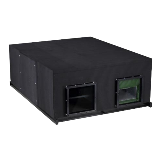
Summarization of Contents
Main PCB Description
Main PCB Ports
Details the various ports and their functions on the main printed circuit board.
Fan Performance
How to Read the Fan Performance Diagram
Explains how to interpret the static pressure vs. air flow characteristic curves.
Fan Performance Diagrams
Provides characteristic curves showing fan performance at different speeds and static pressures.
Installation
Installation Preparation
Details required accessories and initial handling before installation begins.
Selecting the Installation Site
Guidance on choosing an appropriate location for the HRV unit, considering noise and access.
Preparations Before Installation
Checks and preparations including suspension bolts, static pressure, and wiring routes.
Installation Procedures
Step-by-step instructions for securely mounting the unit and connecting essential components.
Wiring
Wiring Warnings
Important safety precautions and compliance guidelines for electrical wiring procedures.
Electrical Data Specifications
Detailed electrical specifications including power supply, current, and wire requirements.
Communication Wiring (Indoor/Outdoor)
Instructions for establishing communication links between the HRV unit and outdoor components.
Communication Wiring (Indoor/Controller)
Details on connecting the HRV unit to various wired controller configurations.
Wired Controller Communication Details
Guidance on securing wiring, sealing connections, and handling controller installation.
Trial Run
Pre-Operation Checks
Essential checks to perform before powering up the unit for the first time.
Pre-Trial Run Checks
Points to verify before commencing the trial run operation.
Control and Operation during Trial Run
Guidance on operating the HRV using the wired controller during the trial run.
Troubleshooting
LED Indicator Explanations
Details the meaning of LED2 flashing patterns and corresponding fault codes.
Temperature Sensor Troubleshooting
Flowcharts for diagnosing and resolving errors related to temperature sensors.
EEPROM Fault Troubleshooting
Procedure for troubleshooting the EEPROM fault, including chip checks.
DC Fan Fault Troubleshooting
Step-by-step guide to diagnose and fix DC fan related faults.
CO2 Sensor Error Troubleshooting
Flowchart for resolving issues with the CO2 sensor and its display.
ODU Communication Failure Troubleshooting
Diagnostic steps for communication issues between the HRV and the outdoor unit.
Controller
Wired Controller KJR-27B/E Operation
Details on the functions and buttons of the KJR-27B/E wired controller.
Wired Controller Buttons and Functions
Explanation of each button's role and operation on the wired controller.
Wired Controller LCD Display
Description of icons and information displayed on the wired controller's LCD screen.
Address Query and Setting
Procedure for querying and setting the address for the wired controller.
Wired Controller Installation and Wiring
Diagrams and connection methods for installing the wired controller.
Wired Controller WDC-120G/WK(A) Operation
Details on the functions and buttons of the WDC-120G/WK(A) wired controller.
WDC-120G/WK(A) Controller Buttons
Explanation of each button's function on the WDC-120G/WK(A) wired controller.
WDC-120G/WK(A) Controller LCD Display
Description of the LCD display elements and their meanings on the WDC-120G/WK(A) controller.


Need help?
Do you have a question about the HRV-D400B and is the answer not in the manual?
Questions and answers