
Related Manuals for Midea CLIVET CRISTALLO


Summary of Contents for Midea CLIVET CRISTALLO
- Page 1 CRISTALLO Serie IM1-XY da 20M a 70M ESSENTIAL 2 Serie IL2-XY da 20M a 70M I - GB M0P300002-03 12-20...
- Page 2 INTRODUZIONE Gentile Cliente, La ringraziamo per aver preferito un prodotto CLIVET. Il modello CRISTALLO / ESSENTIAL 2, da Lei scelto, è un prodotto ad elevate prestazioni, di concezione e tecnologia avanzata, di elevata affidabilità e qualità costruttiva. Le suggeriamo di affidarne la gestione e la manutenzione a personale professionalmente qualificato di Sua fiducia, che utilizzi, quando necessario, solo ricambi originali.
- Page 3 INDICE Generalità ............4 4 Manutenzione ..........23 Avvertenze generali e regole per la 4.1 Pulizia dell’unità interna sicurezza 4.2 Pulizia del filtro dell’aria 1.2 Descrizione componenti del sistema 4.3 Pulizia dell’unità esterna 1.3 Accessori 4.4 Periodi di inutilizzo prolungato 1.4 Identificazione 4.5 Manutenzione a inizio stagione 4.6 Ricerca guasti...
- Page 4 Generalità 1 GENERALITÀ Avvertenze generali e regole per la sicurezza AVVERTENZA – Il presente manuale è proprietà di CLIVET e ne è vietata la riproduzione o la cessione a terzi dei contenuti del presente documento. Tutti i diritti sono riservati. Esso è parte integrante del prodotto; assicurarsi che sia sempre a corredo dell’apparecchio, anche in caso di vendita/trasferimento ad altro proprietario, affinché...
- Page 5 Generalità ATTENZIONE PERICOLO – Quando si collegano le linee frigorifere, evitare l’ingresso nell’unità di sostanze o gas diversi dal refrigerante specificato. La presenza di altri gas o sostanze può ridurre le prestazioni dell’unità e causare un innalzamento anomalo della pressione nel ciclo di refrigerazione. Questo può generare rischi di esplosione e conseguenti lesioni.
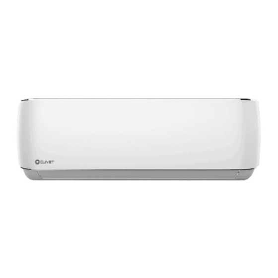
- Page 6 Generalità Descrizione componenti del sistema MONOSplit Fig. 1 A Ingresso aria 7 Collegamento elettrico B Uscita aria 8 Linee frigorifere 1 Piastra di montaggio a parete 9 Alimentazione unità esterna 2 Unità interna 10 Telecomando 3 Feritoia di ventilazione 11 Supporto del telecomando 4 Filtro 12 Display led CRISTALLO 5 Unità...
- Page 7 Generalità Descrizione componenti del sistema MULTISplit 1 x 5 1 x 4 1 x 3 1 x 2 Fig. 2 Unità interna Unità esterna 1 Telaio del pannello 10 Tubo di scarico, tubo di collegamento del refrigerante 2 Griglia di aspirazione aria posteriore 11 Cavo di collegamento 3 Pannello anteriore 12 Valvola di arresto...
- Page 8 Generalità Accessori Il condizionatore è provvisto dei seguenti accessori. Per installarlo, usare tutti i componenti e gli accessori d’installazione specificati. Un’installazione non corretta può provocare perdite d’acqua, scosse elettriche e incendi, o causare il malfunzionamento dell’apparecchio. Descrizione Aspetto Quantità Piastra di montaggio Tassello Vite di fissaggio per piastra di montaggio ST3.9 X 25...
- Page 9 Generalità Identificazione L’unita interna e l’unità esterna sono identificabili attraverso l’etichetta matricolare che riporta i dati tecnici, prestazionali dell’apparecchio e quanto richiesto dalla Legislazione in vigore. Etichetta matricolare Unità interna Fig. 3 PRESTARE CAUTELA La manomissione, l’asportazione, la mancanza delle etichette di identificazione o quant’altro non permetta la sicura identificazione del prodotto, rende difficoltosa qualsiasi operazione di installazione e manutenzione.
- Page 10 Installazione 2 INSTALLAZIONE Installazione - avvertenze preliminari AVVERTENZA Ricevimento del prodotto Prima di installare l’unità interna, consultare l’etichetta sulla confezione del prodotto L’apparecchio viene fornito imballato in più colli. La per controllare che il numero di modello movimentazione deve essere effettuata con appropriati corrisponda a quello dell’unità...
- Page 11 Installazione Installazione unità interna Carica di refrigerante Superficie minima [kg] 41,5 2.4.1 Locale di installazione 44,1 PRESTARE CAUTELA 46,7 L’apparecchio deve essere collocato in un 49,4 locale ben ventilato, con una superficie minima 52,2 che varia in base alla quantità di refrigerante presente.
- Page 12 Installazione Per le distanze dalle pareti e dal soffitto fare riferimento allo schema seguente: Min. 15 cm Min. 12 cm Min. 12 cm Min. 2,3 m Fig. 4 Posizione del display CRISTALLO e del ricevitore del NOTA: Il ricevitore deve essere lasciato libero da ostacoli che segnale da telecomando.
- Page 13 Installazione 2.4.2 Piastra di montaggio Orientamento corretto della piastra di montaggio DIMENSIONI DELLA PIASTRA DI MONTAGGIO La piastra di montaggio è utilizzata per fissare a parete l’unità interna. 348,4 mm 179 mm 101 mm 136 mm Profilo dell’unità interna Foro nel muro Foro nel muro lato lato posteriore posteriore destro,...
- Page 14 Modello 35M Installazione 517,4 mm 144 mm 138 mm Profilo dell’unità interna Foro nel muro Foro nel muro lato lato posteriore posteriore destro, sinistro, 65 mm 65 mm 34 mm 965 mm Modello 53M 553 mm 300 mm 219 mm 53,5 mm 76 mm 53,5 mm...
- Page 15 Installazione 2.4.3 Predisposizione per i tubi di 2 Realizzare il foro nella parete usando una punta da 65 mm (90 mm per i modelli 70M). Il foro dovrà avere collegamento una leggera inclinazione, in modo che l’estremità È necessario realizzare un foro nella parete in cui far esterna sia più...
- Page 16 Installazione 2.4.4 Predisposizione per le linee frigorifere 4 Usando una forbice, tagliare il manicotto isolante in modo da esporre circa 15 cm delle linee frigorifere. Le linee frigorifere si trovano all’interno di un manicotto Questa operazione ha una doppia utilità: isolante fissato sul retro dell’unità.
- Page 17 Installazione 2.4.5 Tubo di drenaggio È VIETATO Nella configurazione predefinita, il tubo di drenaggio è collegato al lato sinistro dell’unità (guardando il retro di – piegare il tubo di drenaggio verso l’alto; quest’ultima). Tuttavia, esso può essere collegato anche – creare punti di ristagno; al lato destro.
- Page 18 Installazione 2.4.6 Collegamenti elettrici Per l’alimentazione e comunicazione tra l’unità interna e Morsettiera quella esterna sono necessari dei cavi con le seguenti Coperchio caratteristiche: Alimentazione Segnale Unità da unità esterna da unità esterna interna n° cavi/sezione n° cavi/sezione Vite 2 x 1,5mm 2 x 1,5mm Fermacavi 2 x 1,5mm...
- Page 19 Installazione 2.4.7 Avvolgere i tubi e i cavi Collegamenti in configurazione MONOSplit È necessario avvolgere insieme i tubi del refrigerante, il tubo di drenaggio e i cavi elettrici; questo permette Morsettiera unità INTERNA Morsettiera unità INTERNA di ridurre l’occupazione di spazio, proteggerli e isolarli prima di passarli attraverso il foro nella parete.
- Page 20 Installazione 2.4.8 Montaggio dell’unità interna 4 Lasciare esposto il punto di collegamento dei tubi per poter controllare l’assenza di perdite (vedere CASO “A”: Se è stato installato un nuovo tubo di la sezione “3.2 Controllo di dispersioni elettriche e collegamento all’unità esterna, procedere come segue: perdite di gas”...
- Page 21 3 USO Significato dei codici del display Icona Descrizione Descrizione componenti del sistema Si visualizza per 3 secondi quando: • si imposta il timer di accensione (TIMER • vengono attivate le funzioni SWING, TURBO o SILENCE Si visualizza per 3 secondi quando: •...
- Page 22 Installazione Telecomando ON/OFF TEMP + ON/OFF TEMP Tasto di accensione/ Aumenta la temperatura Tasto di accensione/ Aumenta la temperatura spegnimento dell’unità a incrementi di 1°C. spegnimento dell’unità a incrementi di 1°C. La temperatura La temperatura massima è di 30°C massima è di 30°C Mode ON/OFF Fan MODE...
- Page 23 Installazione 3.4.1 Altre funzioni 3.4.2 Regolazione dell’angolazione del flusso d’aria – Riavvio automatico REGOLAZIONE DELL’ANGOLAZIONE l’alimentazione elettrica dell’unità viene interrotta, al suo ripristino l’unità si riavvierà VERTICALE DEL FLUSSO D’ARIA automaticamente con le ultime impostazioni. Con l’unità accesa, usare il tasto per regolare la direzione (angolazione verticale) del flusso d’aria.
- Page 24 Installazione Funzionamento manuale (senza telecomando) È VIETATO regolare le feritoie di ventilazione con le mani, Nel caso in cui il telecomando non funzioni, l’unità perché così facendo si potrebbe alterare il può essere azionata manualmente con il tasto di sincronismo. In questo caso, spegnere l’unità comando manuale situato sull’unità...
- Page 25 Manutenzione 4 MANUTENZIONE È VIETATO È buona norma pulire periodicamente sia le parti asciugare il filtro esponendolo alla luce diretta interne che quelle esterne dell’apparecchio. Questo ne del sole. Il filtro potrebbe restringersi garantisce il buon funzionamento e la durata nel tempo. Eseguire la manutenzione periodica dell’apparecchio 1 Sollevare il pannello anteriore dell’unità...
- Page 26 Manutenzione Periodi di inutilizzo prolungato 5 Sciacquare il filtro con acqua pulita e scuoterlo per eliminare l’acqua in eccesso. Se si prevede di non utilizzare il condizionatore per un periodo prolungato, procedere come segue: Pulire tutti i filtri Attivare il modo Ventilazione fino alla completa asciugatura dell’unità...
- Page 27 Manutenzione Ricerca guasti ATTENZIONE PERICOLO Se si dovesse verificare UNA QUALSIASI delle seguenti condizioni, spegnere subito l’unità. – Il cavo di alimentazione è danneggiato o è insolitamente caldo. – Si sente un odore di bruciato. – L’unità emette rumori forti o anomali. –...
- Page 28 Manutenzione 4.6.2 Anomalie e rimedi In caso di problemi, eseguire i seguenti controlli prima di rivolgersi a un centro di assistenza. Anomalie Possibili cause Rimedi È possibile che la temperatura impostata sia più alta della temperatura ambiente Impostare una temperatura più bassa del locale Lo scambiatore di calore dell’unità...
- Page 29 Manutenzione Codici di errore unità interna Numero di Indicatore Codice errore Causa lampeggi per timer secondo Errore della EEPROM (Electrically Erasable Programmable Read- Only Memory) dell’unità interna Errore di comunicazione tra unità interna ed esterna Malfunzionamento della velocità del ventilatore dell’unità interna Errore del sensore di temperatura ambiente interna Errore del sensore di temperatura della serpentina dell’evaporatore...
- Page 30 Smaltimento 5 SMALTIMENTO Il produttore è iscritto al Registro Nazionale AEE, in RAEE professionali: tutti i RAEE diversi da quelli provenienti conformità all’attuazione della direttiva 2012/19/UE e delle dai nuclei domestici di cui al punto sopra. relative norme nazionali vigenti sui rifiuti di apparecchiature Queste apparecchiature possono contenere: elettriche ed elettroniche.
- Page 31 Allegati 6 ALLEGATI Schemi elettrici unità interna SERIE GRANDEZZA 20M - 27M - 35M IM1-XY 53M - 70M 20M - 27M - 35M IL2-XY 53M - 70M...
- Page 32 Allegati Dichiarazione di conformità DECLARATION OF CONFORMITY EU DICHIARAZIONE DI CONFORMITÀ UE KONFORMITÄTSERKLÄRUNG EU DECLARATION DE CONFORMITE EU DECLARACIÓN DE CONFORMIDAD EU E DECLARE UNDER OUR SOLE RESPONSIBILITY THAT THE MACHINE ICHIARIAMO SOTTO LA NOSTRA SOLA RESPONSABILITÀ CHE LA MACCHINA IR ERKLÄREN EIGENVERANTWORTLICH, DASS DIE ASCHINE OUS DÉCLARONS SOUS NOTRE SEULE RESPONSABILITÉ...
- Page 33 Allegati DECLARATION OF CONFORMITY EU DICHIARAZIONE DI CONFORMITÀ UE KONFORMITÄTSERKLÄRUNG EU DECLARATION DE CONFORMITE EU DECLARACIÓN DE CONFORMIDAD EU E DECLARE UNDER OUR SOLE RESPONSIBILITY THAT THE MACHINE ICHIARIAMO SOTTO LA NOSTRA SOLA RESPONSABILITÀ CHE LA MACCHINA IR ERKLÄREN EIGENVERANTWORTLICH, DASS DIE ASCHINE OUS DÉCLARONS SOUS NOTRE SEULE RESPONSABILITÉ...
- Page 34 Allegati...
- Page 35 Allegati...
- Page 36 DA 30 ANNI OFFRIAMO SOLUZIONI PER IL COMFORT SOSTENIBILE E IL BENESSERE DELL’INDIVIDUO E DELL’AMBIENTE www.clivet.com vendita e assistenza PRONTO CLIVET ASSISTENZA DEDICATA: PRONTO CLIVET Assistenza SPLIT Clivet (solo Italia): Tel. 041/5099169 Lu-Ve 09:00-20:00, Sa 09:00-12:00 (festivi esclusi) split@clivet.support CLIVET SPA Via Camp Lonc 25, Z.I.
- Page 37 CRISTALLO IM1-XY series from 20M to 70M ESSENTIAL 2 IL2-XY series from 20M to 70M...
- Page 38 INTRODUCTION Dear Customer, Thank you for choosing a CLIVET product. The CRISTALLO / ESSENTIAL 2 model which you have chosen, is a high performance product of advanced design and technology, high reliability and quality construction. We suggest that you entrust its management and maintenance to professionally qualified personnel you trust, who, when necessary, only use original spare parts.
- Page 39 INDEX General Details ..........4 4 Maintenance ........... 25 General warnings and safety rules 4.1 Cleaning the indoor unit 1.2 Description of SINGLESplit system 4.2 Cleaning the air filter components 4.3 Cleaning the outdoor unit 1.3 Description of MULTISplit system 4.4 Extended periods of inactivity components 4.5 Maintenance at the start of the season...
- Page 40 General Details 1 GENERAL DETAILS General warnings and safety rules WARNING – This manual is the property of CLIVET and reproduction or transfer to third parties of the contents of this document is prohibited. All rights reserved. It is an integral part of the product; make sure that it is always supplied with the appliance, even in case of sale/transfer to another owner, so that it can be consulted by the user or by personnel authorized to carry out maintenance and repairs.
- Page 41 General Details CAUTION DANGER – When connecting refrigerant piping,keep substances or gases other than the specified refrigerant from entering the unit. The presence of other gases or substances can reduce unit performance and cause an abnormal increase in pressure in the refrigeration cycle. This can lead to explosion hazards and resulting injuries. –...
- Page 42 General Details Description of SINGLESplit system components Fig. 1 A Air inlet 7 Electrical connection B Air outlet 8 Refrigerant piping 1 Wall mounting plate 9 Outdoor unit power supply 2 Indoor unit 10 Remote control 3 Ventilation louver 11 Remote control support 4 Filter 12 Display led CRISTALLO 5 Outdoor unit...
- Page 43 General Details Description of MULTISplit system components 1 x 5 1 x 4 1 x 3 1 x 2 Fig. 2 Indoor unit Outdoor unit 1 Panel frame 10 Drain pipe, refrigerant connection pipe 2 Rear air intake grille 11 Connection cable 3 Front panel 12 Stop valve 4 Purifier filter and air filter (on the back)
- Page 44 General Details Accessories The air conditioner is equipped with the following accessories. Use all specified installation components and accessories to install it. Incorrect installation may cause water leakage, electric shock and fire, or cause the unit to malfunction. Illustration Waiting Quantity Mounting plate Gusset...
- Page 45 General Details Identification The indoor unit and the outdoor unit can be identified by the serial number label that shows the technical and performance data of the unit and what is required by the legislation in force. Serial number label Indoor unit Fig.
- Page 46 Installation 2 INSTALLATION Installation - preliminary warnings WARNING Product receiving Before installing the indoor unit, consult the label on the product package to check that the The appliance is supplied packed in several parcels. model number matches the model number of Handling must be carried out by appropriate means in the outdoor unit.
- Page 47 Installation Indoor unit installation Refrigerant charge Minimum surface [kg] 41.5 2.4.1 Installation room 44.1 CAUTION 46,7 appliance must placed 49.4 well-ventilated room, with a minimum surface 52.2 area that varies according to the amount of refrigerant present. 55.1 58.0 To calculate the minimum area of the installation room, 7.956 61.0 proceed as described below:...
- Page 48 Installation Please refer to the following diagram for wall and ceiling distances: Min 15 cm Min 12 cm Min 12 cm Min 2.3 m Fig. 4 Position of the display CRISTALLO and remote control NOTE: The receiver must be left free of obstacles that could signal receiver.
- Page 49 Installation 2.4.2 Mounting plate Correct orientation of the mounting plate MOUNTING PLATE DIMENSIONS The mounting plate is used to fix the indoor unit to the wall. 348.4 mm 179 mm 101 mm 136 mm Indoor unit profile Hole in the wall Hole in the wall on on the left rear the right rear side,...
- Page 50 35M Model Installation 517.4 mm 144 mm 138 mm Indoor unit profile Hole in the wall Hole in the wall on on the left rear the right rear side, side, 65 mm 65 mm 34 mm 965 mm 53M Model 553 mm 300 mm 219 mm...
- Page 51 Installation 2.4.3 Preparation for connection pipes 2 Drill the hole in the wall using a 65 mm drill bit (90 mm for 70M models). The hole should have a slight It is necessary to make a hole in the wall where the inclination, so that the outer end is lower than the inner refrigerant piping, drainage pipe and electrical cables one by about 5-7 mm.
- Page 52 Installation 2.4.4 Preparation for refrigerant piping 4 Using scissors, cut the insulation sleeve so that about 15 cm of the refrigerant piping is exposed. The refrigerant piping is located inside an insulating This operation has a double utility: sleeve fixed on the back of the unit. It is necessary to –...
- Page 53 Installation 2.4.5 Drainage pipe IT IS PROHIBITED TO In the default configuration, the drainage pipe is connected to the left side of the unit (looking at the back of the unit). – bend the drainage pipe upwards; However, it can also be connected to the right side. –...
- Page 54 Installation 2.4.6 Electrical connections Cables with the following characteristics are required for Terminal block power supply and communication between the indoor Cover and outdoor units: Power supplied Signal from outdoor Indoor from outdoor unit unit unit n° cables/cross n° cables/cross Screw section section...
- Page 55 Installation 2.4.7 Wrap the pipes and cables Connections in SINGLESplit configuration It is necessary to wrap the coolant pipes, drainage pipe and electrical cables together; this reduces the space INDOOR unit terminal block Morsettiera unità INTERNA occupied, protects them and insulates them before passing them through the hole in the wall.
- Page 56 Installation 2.4.8 Mounting the indoor unit 5 After checking for leaks, wrap the connection point with insulating tape. CASE “A”: If you have installed a new connection pipe 6 Remove the bracket or wedge that holds the unit up. to the outdoor unit, proceed as follows: 7 Applying uniform pressure, push on the lower half of 1 Check that the ends of the coolant pipes are closed the unit.
- Page 57 3 USE Meaning of the display codes Icon Illustration Description of system components It displays for 3 seconds when: • you set the start-up timer (TIMER ON) • SWING, TURBO or SILENCE functions are activated It displays for 3 seconds when: •...
- Page 58 Remote control ON/OFF TEMP + ON/OFF TEMP Power button/ Increase the temperature Tasto di accensione/ Aumenta la temperatura switching off the unit in 1°C increments. spegnimento dell’unità a incrementi di 1°C. The temperature La temperatura maximum is 30°C massima è di 30°C Mode ON/OFF Fan MODE...
- Page 59 3.4.1 Other functions 3.4.2 Airflow angle adjustment – Automatic restart ADJUSTING THE VERTICAL AIR FLOW ANGLE If the power supply to the unit is interrupted, the With the unit turned on, use button to adjust airflow unit will automatically restart with the last settings direction (vertical angle).
- Page 60 ADJUSTING THE HORIZONTAL AIR FLOW ANGLE Manual operation (without remote control) With the unit turned on, use the button to adjust the direction (horizontal angle) of airflow. If the remote control does not work, the unit can be 1 Press the button once to activate the ventilation operated manually with the manual control button louver.
- Page 61 Maintenance 4 MAINTENANCE IT IS PROHIBITED TO It is good practice to periodically clean both the internal dry the filter by exposing it to direct sunlight. and external parts of the appliance. This guarantees its The filter may shrink proper functioning and durability. Carry out periodic maintenance of the appliance in 1 Lift the front panel of the indoor unit.
- Page 62 Maintenance Extended periods of inactivity 5 Rinse the filter with clean water and shake it to remove excess water. If you do not plan to use the air conditioner for an extended period of time, proceed as follows: Clean all filters Activate the Ventilation mode until the unit is completely dry Fig.
- Page 63 Maintenance Troubleshooting CAUTION DANGER If any of the following conditions occur, turn the unit off immediately. – The power cord is damaged or unusually hot. – You can smell burning. – The unit makes loud or abnormal noises. – A fuse blows or the circuit breaker trips frequently. –...
- Page 64 Maintenance 4.6.2 Abnormalities and remedies If problems occur, please check the following before contacting a service centre. Anomalies Possible causes Remedies The set temperature may be higher than Set a lower temperature the room temperature The heat exchanger of the indoor or Clean the heat exchanger (Service Centre) outdoor unit is dirty Remove the filter and clean it following...
- Page 65 Maintenance Indoor unit error codes Number of Timer Error code Cause flashes per indicator second EEPROM (Electrically Erasable Programmable Read-Only Memory) error of the indoor unit Communication error between an indoor unit and the outdoor unit Malfunction of the indoor unit fan speed Internal room temperature sensor error Evaporator coil temperature sensor error Malfunctioning of the refrigerant leak detection system...
- Page 66 Disposal 5 DISPOSAL The manufacturer is registered on the National EEE Register, Professional WEEE: all WEEE which comes from something in compliance with implementation of Directive 2012/19/EU other than private households. and pertinent national regulations on electrical and electronic This equipment may contain: equipment waste.
- Page 67 Attachments 6 ATTACHMENTS Indoor unit wiring diagrams SERIE SIZE 20M - 27M - 35M IM1-XY 53M - 70M 20M - 27M - 35M IL2-XY 53M - 70M...
- Page 68 Attachments Conformance Statement DECLARATION OF CONFORMITY EU DICHIARAZIONE DI CONFORMITÀ UE KONFORMITÄTSERKLÄRUNG EU DECLARATION DE CONFORMITE EU DECLARACIÓN DE CONFORMIDAD EU E DECLARE UNDER OUR SOLE RESPONSIBILITY THAT THE MACHINE ICHIARIAMO SOTTO LA NOSTRA SOLA RESPONSABILITÀ CHE LA MACCHINA IR ERKLÄREN EIGENVERANTWORTLICH, DASS DIE ASCHINE OUS DÉCLARONS SOUS NOTRE SEULE RESPONSABILITÉ...
- Page 69 Attachments DECLARATION OF CONFORMITY EU DICHIARAZIONE DI CONFORMITÀ UE KONFORMITÄTSERKLÄRUNG EU DECLARATION DE CONFORMITE EU DECLARACIÓN DE CONFORMIDAD EU E DECLARE UNDER OUR SOLE RESPONSIBILITY THAT THE MACHINE ICHIARIAMO SOTTO LA NOSTRA SOLA RESPONSABILITÀ CHE LA MACCHINA IR ERKLÄREN EIGENVERANTWORTLICH, DASS DIE ASCHINE OUS DÉCLARONS SOUS NOTRE SEULE RESPONSABILITÉ...
- Page 70 Attachments...
- Page 71 Attachments...
- Page 72 FOR 30 YEARS WE HAVE BEEN OFFERING SOLUTIONS FOR SUSTAINABLE COMFORT THE WELL-BEING OF PEOPLE AND THE ENVIRONMENT www.clivet.com sales and service CLIVET SPA Via Camp Lonc 25, Z.I. Villapaiera 32032 Feltre (BL) - Italy Tel. +39 0439 3131 - Fax +39 0439 313300 info@clivet.it...
- Page 73 CRISTALLO Série IM1-XY de 20M à 70M ESSENTIAL 2 Série IL2-XY de 20M à 70M...
- Page 74 INTRODUCTION Cher Client, Merci d'avoir choisi un produit CLIVET. Le modèle CRISTALLO / ESSENTIAL 2, que vous avez choisi, est un produit aux hautes performances, avec une conception et une technologie de pointe, d’une excellente fiabilité et d’une fabrication de qualité. Nous vous suggérons de confier la gestion et l’entretien à...
- Page 75 INDEX Généralités ............. 4 4 Entretien ............25 Avertissements généraux et consignes 4.1 Nettoyage de l'unité interne de sécurité 4.2 Nettoyage du filtre à air 1.2 Description des composants du système 4.3 Nettoyage de l’unité externe MONOSplit 4.4 Périodes d'inutilisation prolongée 1.3 Description des composants du système 4.5 Entretien en début de saison MULTISplit...
- Page 76 Généralités 1 GÉNÉRALITÉS Avertissements généraux et consignes de sécurité MISE EN GARDE – Ce manuel est la propriété de CLIVET et sa reproduction ou le transfert à des tiers du contenu de ce document est interdit. Tous les droits sont réservés. Il fait partie intégrante du produit ; il faut donc s’assurer qu'il est toujours fourni avec l'appareil, même en cas de vente/transfert à...
- Page 77 Généralités ATTENTION DANGER – Lors du raccordement des lignes frigorifiques, éviter l’entrée de substances ou de gaz autres que le réfrigérant spécifié dans l'unité. La présence d'autres gaz ou de substances peut réduire les performances de l'unité et provoquer une augmentation anormale de la pression dans le cycle de réfrigération. Cela peut entraîner des risques d'explosion et des blessures consécutives.
- Page 78 Généralités Description des composants du système MONOSplit Fig. 1 A Entrée air 7 Branchement électrique B Sortie air 8 Lignes frigorifiques 1 Plaque pour le montage mural 9 Alimentation des unités externes 2 Unité interne 10 Télécommande 3 Volet de ventilation 11 Support de la télécommande 4 Filtre 12 Écran LED CRISTALLO...
- Page 79 Généralités Description des composants du système MULTISplit 1 x 5 1 x 4 1 x 3 1 x 2 Fig. 2 Unité interne Unité externe 1 Cadre du panneau 10 Tuyau de vidange, tuyau de raccordement du réfrigérant 2 Grille d'admission d'air arrière 11 Câble de raccordement 3 Panneau avant 12 Vanne d'arrêt...
- Page 80 Généralités Accessoires Le climatiseur est équipé des accessoires suivants. Pour l'installer, il faut utiliser toutes les pièces et accessoires d'installation spécifiés. Une mauvaise installation incorrecte entraîner des fuites d'eau, des décharges électriques et des incendies, ou provoquer un dysfonctionnement de l'appareil. Description Aspect Quantité...
- Page 81 Généralités Identification L'unité interne et l'unité externe sont identifiables au moyen de l'étiquette du numéro de série qui indique les données techniques, les performances de l'appareil et ce qui est requis par la législation en vigueur en la matière. Étiquette du numéro de série Unité...
- Page 82 Installation 2 INSTALLATION Installation - mises en garde préliminaires MISE EN GARDE Réception du produit Avant d'installer l'unité interne, il faut vérifier l'étiquette située sur l'emballage du produit de L'appareil est livré emballé dans plusieurs colis. manière à contrôler que le numéro du modèle La manutention doit être effectuée avec des engins correspond à...
- Page 83 Installation Installation de l’unité interne Charge de réfrigérant Surface minimale [kg] 44,1 2.4.1 Pièce pour l’Installation 46,7 FAIRE ATTENTION 49,4 L'appareil doit être placé dans une pièce bien 52,2 aérée, avec une surface minimale qui varie en 55,1 fonction de la quantité de réfrigérant présent. 58,0 Pour calculer la surface minimale de la pièce d'installation, 7,956...
- Page 84 Installation Pour les distances des murs et du plafond, il faut se référer schéma suivant : Min. 15 cm Min. 12 cm Min. 12 cm Min. 2,3 m Fig. 4 Position de l’écran CRISTALLO et du récepteur du signal REMARQUE : Le récepteur doit être mis à...
- Page 85 Installation 2.4.2 Plaque de montage Orientation correcte de la plaque de montage DIMENSIONS DE LA PLAQUE DE MONTAGE La plaque de montage est utilisée pour fixer l'unité interne au mur. 348,4 mm 179 mm 101 mm 136 mm Profil de l'unité interne Trou dans le Trou dans le mur...
- Page 86 Modèle 35M Installation 517,4 mm 144 mm 138 mm Profil de l'unité interne Trou dans le Trou dans le mur mur côté arrière côté arrière droit, gauche, 65 mm 65 mm 34 mm 965 mm Modèle 53M 553 mm 300 mm 219 mm 53,5 mm 76 mm...
- Page 87 Installation 2.4.3 Prédisposition pour les tuyaux de 2 Percer le trou dans le mur à l'aide d'un foret de 65 mm (90 mm pour les modèles 70M). Le trou doit avoir une raccordement légère inclinaison, de sorte que l'extrémité externe Il est nécessaire de faire un trou dans le mur pour faire passer soit plus basse que celle interne d’environ 5-7 mm.
- Page 88 Installation 2.4.4 Prédisposition pour les lignes frigorifiques 4 À l'aide de ciseaux, couper le manchon isolant de manière à dégager environ 15 cm des lignes Les lignes frigorifiques sont situées à l'intérieur d'un frigorifiques. Cette opération a un double utilité : manchon isolant fixé...
- Page 89 Installation 2.4.5 Tuyau de drainage IL EST INTERDIT Dans la configuration par défaut, le tuyau de drainage est raccordé au côté gauche de l'unité (en regardant l'arrière – de plier le tuyau de drainage vers le haut ; de l'unité). Cependant, il peut également être raccordé –...
- Page 90 Installation 2.4.6 Branchements électriques Pour l'alimentation électrique et la communication Bornier entre les unités interne et externe, des câbles ayant les Couvercle caractéristiques suivantes sont nécessaires : Alimentation Signal électrique Unité de l'unité externe de l'unité externe interne n° câbles/section n°...
- Page 91 Installation Branchements en configuration MONOSplit 2.4.7 Enrouler les tuyaux et les câbles Il faut enrouler les tuyaux du réfrigérant, le tuyau de drainage et les câbles électrique ; cela permet de réduire Morsettiera unità INTERNA Bornier unité INTERNE l'occupation de l'espace, de les protéger et de les isoler avant de les faire passer à...
- Page 92 Installation 2.4.8 Montage de l'unité interne 4 Laisser exposé le point de raccordement du tuyau afin de pouvoir contrôler l’absence de fuites (voir la CAS « A » : Si un nouveau tuyau de raccordement à section « 3.2 Contrôle des dispersions électriques et l'unité...
- Page 93 Utilisation 3 UTILISATION Signification des codes à l’écran Icône Description Description des composants du système S'affiche pendant 3 secondes lors : • de la configuration du timer de marche (TIMER ON) • de l’activation des fonctions SWING, TURBO ou SILENCE S'affiche pendant 3 secondes lors : •...
- Page 94 Utilisation Télécommande ON/OFF ON/OFF TEMP + TEMP Tasto di accensione/ Touche de marche/arrêt Augmente la température Aumenta la temperatura spegnimento dell’unità de l’unité par paliers de 1°C. a incrementi di 1°C. La température maximale La temperatura est de 30°C massima è di 30°C Mode ON/OFF Fan MODE...
- Page 95 Utilisation 3.4.1 Autres fonctions 3.4.2 Réglage de l'angle du flux d'air – Redémarrage automatique RÉGLAGE DE L'ANGLE VERTICAL DU FLUX D'AIR Si l'alimentation électrique de l'unité est interrompue, Avec l’unité allumée, utiliser la touche pour régler le celle-ci redémarrera automatiquement avec les sens (angle vertical) du flux d'air.
- Page 96 Utilisation Fonctionnement manuel (sans télécommande) IL EST INTERDIT de régler les volets de ventilation avec Si la télécommande ne fonctionne pas, l'unité peut les mains, car cela pourrait modifier le être actionnée manuellement à l'aide de la touche synchronisme. Dans ce cas, il faut arrêter l’unité de commande manuelle située sur l'unité...
- Page 97 Entretien 4 ENTRETIEN ATTENTION DANGER Il est recommandé de nettoyer périodiquement les Lors de la dépose du filtre, il faut éviter de parties internes et externes de l'unité. Cela garantit son toucher les parties métalliques de l'unité. bon fonctionnement et sa durée dans le temps. Les bords métalliques peuvent être tranchants.
- Page 98 Entretien Périodes d'inutilisation prolongée 5 Rincer le filtre à l'eau claire et le secouer pour éliminer l'excès d'eau. En cas de décision de ne pas utiliser le climatiseur pendant une période prolongée, il faut procéder comme suit : Nettoyer tous Actionner le mode Ventilation les filtres jusqu'au séchage complet de l'unité...
- Page 99 Entretien Diagnostic des pannes ATTENTION DANGER Si L’UNE des conditions suivantes se produit, il faut immédiatement éteindre l’unité. – Le cordon d'alimentation est endommagé ou est anormalement chaud. – Il y a une odeur de brûlé. – L'unité émet des bruits forts ou anormaux. –...
- Page 100 Entretien 4.6.2 Anomalies et remèdes En cas de problèmes, il faut effectuer les contrôles suivants avant de contacter un centre de service. Anomalies Causes possibles Remèdes Il est possible que la température configurée soit supérieure à la Configurer une température plus basse température ambiante de la pièce L'échangeur de chaleur de l'unité...
- Page 101 Entretien Codes d'erreur de l'unité interne Nombre de Indicateur Code erreur Cause clignotements timer par seconde Erreur de l’EEPROM (Electrically Erasable Programmable Read-Only Memory [mémoire en lecture seule programmable effaçable électriquement]) de l'unité interne Erreur de communication entre l’unité interne et l’unité externe Dysfonctionnement de la vitesse du ventilateur de l'unité...
- Page 102 Élimination 5 ÉLIMINATION Le producteur est inscrit dans le Registre National EEE, Les DEEE professionnels : tous les DEEE autres que ceux conformément à l’application de la directive 2012/19/UE et provenant des foyers domestiques mentionnés au point des réglementations nationales correspondantes en vigueur ci-dessus.
- Page 103 Pièces jointes 6 PIÈCES JOINTES Schémas électrique de l'unité interne SÉRIE TAILLE 20M - 27M - 35M IM1-XY 53M - 70M 20M - 27M - 35M IL2-XY 53M - 70M...
- Page 104 Pièces jointes Déclaration de conformité DECLARATION OF CONFORMITY EU DICHIARAZIONE DI CONFORMITÀ UE KONFORMITÄTSERKLÄRUNG EU DECLARATION DE CONFORMITE EU DECLARACIÓN DE CONFORMIDAD EU E DECLARE UNDER OUR SOLE RESPONSIBILITY THAT THE MACHINE ICHIARIAMO SOTTO LA NOSTRA SOLA RESPONSABILITÀ CHE LA MACCHINA IR ERKLÄREN EIGENVERANTWORTLICH, DASS DIE ASCHINE OUS DÉCLARONS SOUS NOTRE SEULE RESPONSABILITÉ...
- Page 105 Pièces jointes DECLARATION OF CONFORMITY EU DICHIARAZIONE DI CONFORMITÀ UE KONFORMITÄTSERKLÄRUNG EU DECLARATION DE CONFORMITE EU DECLARACIÓN DE CONFORMIDAD EU E DECLARE UNDER OUR SOLE RESPONSIBILITY THAT THE MACHINE ICHIARIAMO SOTTO LA NOSTRA SOLA RESPONSABILITÀ CHE LA MACCHINA IR ERKLÄREN EIGENVERANTWORTLICH, DASS DIE ASCHINE OUS DÉCLARONS SOUS NOTRE SEULE RESPONSABILITÉ...
- Page 106 Pièces jointes...
- Page 107 Pièces jointes...
- Page 108 DEPUIS PLUS DE 30 ANS, NOUS OFFRONS DES SOLUTIONS POUR UN CONFORT DURABLE ET LE BIEN-ÊTRE DES PERSONNES ET DE L’ENVIRONNEMENT ww.clivet.com vente et assistance CLIVET SPA Via Camp Lonc 25, Z.I. Villapaiera - 32032 Feltre (BL) - Italie Tél. +39 0439 3131 - Fax +39 0439 313300 info@clivet.it...
Need help?
Do you have a question about the CLIVET CRISTALLO and is the answer not in the manual?
Questions and answers