
Related Manuals for East Tester ET510


Summary of Contents for East Tester ET510
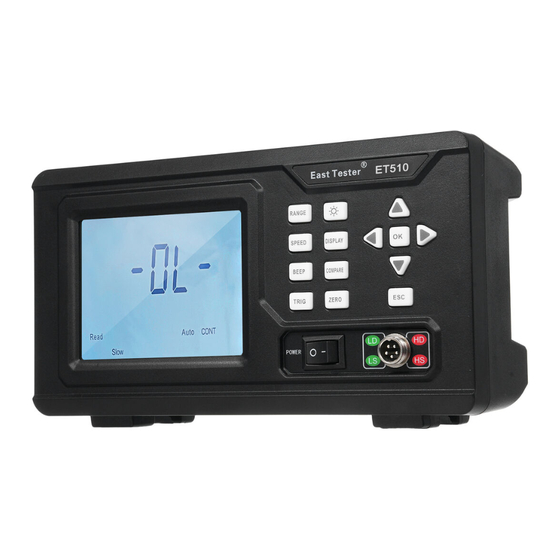
- Page 1 East Tester ® ET51X Series DC Low Resistance Tester User Manual Hangzhou Zhongchuang Electron Co.,Ltd.
-
Page 2: Table Of Contents
Contents Chapter 1 Precautions ................. 2 1.1 Check Items Inside the Package ........... 2 1.2 Precautions ................3 Chapter 2 Product Overview ...............5 2.1 Product Description .............. 5 2.2 Introduction to Product Functions ..错误!未定义书签。 2.3 Product Specifications ......错误!未定义书签。 2.4 Introduction to the Button Area ..错误!未定义书签。 Chapter 3 Measurement Operations and Sorting Settings错误!未定义书签。... -
Page 3: Chapter 1 Precautions
Chapter 1 Precautions 1.1 Check Items Inside the Package After receiving the product you’ve purchased, please check it first. Please check it in accordance with the list provided. If there are any items missing, please contact our company or the distributor to protect your rights. -
Page 4: Precautions
1.2 Precautions 1.2.1 Conditions of Use 1) Temperature and humidity range: Temperature: 5 to 40 ℃, Humidity: Below 80% RH (without standing water or condensation). 2) Temperature and humidity range ensuring accuracy: Temperature: 23 ± 5 ℃. Humidity: Below 80% RH (without standing water or condensation). - Page 5 certain tilt angle; The instrument should be used in a stable, dust-free, shaded and dry environment. 1.2.2 Power Supply The power supply voltage ranges from 100 to 240V, with a power supply frequency of 50/60Hz and a power of <15VA. 1.2.3 Precautions during Testing 1) Safety should always be the top priority under any circumstances.
-
Page 6: Chapter 2 Product Overview
Chapter 2 Product Overview 2.1 Product Description The ET51X series DC low resistance tester is designed for measuring various DC medium and low resistances, including winding resistances found in transformers, contact resistances in relays, conductor resistances in cables, interconnection resistances between metal components, as well as various other types of DC resistances in fuses, conductive rubber, etc. -
Page 7: Introduction To Product Functions
2.2 Introduction to Product Functions Introduction to the Front Area (1) Interface Display Area It displays measurement data and the current function status. (2) Function Button Area It includes Range, Backlight, direction buttons, and other function... - Page 8 buttons. (3) Power and Wiring Area Power switch and test probe terminal. Introduction to the Back Area (4) Power Terminal It is designed for connecting three-core power cord. (5) External Communication Interface Available interfaces are RS232, RS485, and HANDLER, with RS485 being an optional feature.
-
Page 9: Product Specifications
2.3 Product Specifications 2.3.1 Technical Specifications Model ET510 ET511 ET512 ET513 Measurement 0~ 5kΩ 0~ 20kΩ 0~ 200kΩ 0~ 2MΩ Range Basic 0.1% Reading+ 3 digits (Minimum resolution: 10uΩ) Accuracy Maximum Test 100mA Current Display Mode Direct reading/percentage Test Speed Slow: 8 times/s, Fast: 15times/s Sorting Standard... -
Page 10: Introduction To The Button Area
2.4 Introduction to the Button Area 2.4.1 Function Buttons 1) Range Button (RANGE): For choosing either the Auto or Locked mode. In the Locked mode, please adjust the range size using the left/right or up/down buttons. 2) Speed Button (SPEED): For switching measurement speed. 3) Beep Button (BEEP): For choosing whether the Buzzer sounds under U_H_Lim/Pass/D_L_ Lim conditions, or disable the beep function. - Page 11 Note: "U_H_Lim" indicates values exceeding the upper limit, "Pass" indicates values falling within the upper and lower limits, and "D_L_ Lim" indicates values smaller than the lower limit. 4) Trigger Button (TRIG): For switching between continuous and single trigger mode. Continuous triggering involves continuous measurement, while single triggering requires selection between manual and external triggering.
- Page 12 After activation, the set values are preserved even in the event of power outage, but the Sorting function must be re-enabled to start the comparison process. 8) Zeroing Button (ZERO): Zeroing is generally not required, but it can be activated using the ZERO button. Before pressing the button, please ensure the two test leads are connected as depicted in the diagram below: After ensuring the wires are properly connected, press the zero key and...
- Page 13 2.4.2 Direction Button Area The Direction Button Area comprises direction buttons, an OK button and an ESC button. The direction buttons are designed for navigating the cursor (depicted as a triangle) in functional mode and adjusting the cursor (numerical values in flashing mode) within parameters.
-
Page 14: Test Flow Chart
Chapter 3 Measurement Operations and Sorting Settings 3.1 Test Flow Chart... -
Page 16: Introduction To Key Steps
3.2 Introduction to Key Steps 3.2.1 Connect Test Clips Align the test lead with the notch on the test end (as depicted below) and then connect it. 3.2.2 Connect the Tested Object Clip the two jaws of the Kelvin clip onto both ends of the tested object(Rx), and then make the connection as illustrated in the diagram below. -
Page 17: Sorting Settings
3.2.3 Read Measurement Results In continuous trigger mode without the sorting function being enabled, measurement results can be read directly from the display screen as shown below: In single trigger mode with 232/485 connected, results can be read through the obtained return values. 3.3 Sorting Settings 3.3.1 Data Display Status The sorting function offers two data display modes: direct reading... - Page 18 3.3.2 Nominal Resistance Deviation Percentage In percentage display mode, users can set nominal resistance values to display the deviation percentage between the resistance and the nominal value, and can also set the upper and lower percentage limits within the sorting function. By default, configuration starts from the least significant bit, with the most significant bit reserved for symbol display.
- Page 19 Press the "Display" button to set the display mode. After selecting the percentage, it will directly navigate to the nominal value settings in the comparison function. Press the OK button to sequentially navigate the Upper Limit, Lower Limit, and Enable. In the case of direct reading mode, users need to press the sorting button.
-
Page 20: Chapter 4 External Interfaces
(1) When the "U_H_Lim" is selected, the Buzzer will sound for 50ms if the measured resistance value is greater than the configured upper limit. (2) When the "Pass" is selected, the Buzzer will sound for 50ms if the measured resistance value is within the configured upper and lower limits. -
Page 21: Rs232/Rs485 Interfaces
requirements for the interface, as this may cause damage to the interface or even the instrument. When connecting, ensure the connectors at both ends of the communication cable are securely connected. Loose connections may lead to communication failures or other accidents. According to the RS-232C standard, if a MODEM is not used and the symbol distortion remains below 4%, the maximum transmission distance between data communication equipment and data terminals is... - Page 22 RX connected to TX, TX to RX, and GND to GND. The communication speed is fixed at 9600bps, with 8 data bits, 1 stop bit, and no parity bit. Fig. 6.1 Wiring Method for the Instrument's RS232 Interface Signal Abbreviation Corresponding Pin Transmit Receive...
-
Page 23: Rs232/485 Commands
between both ends. The communication speed is fixed at 9600bps, with 8 data bits, 1 stop bit, and no parity bit. 4.3 RS232/485 Commands Refer to the SCPI Programming Manual for details. 4.4 HANDLER (Sorting) Interface The comparison interface, also known as the HANDLER interface, enables the instrument to work in conjunction with mechanical handling systems, such as the automatic sorting system, for components. - Page 24 Description Floating, not connected Pin 2 is designed for sorting "U_H_Lim" signals, which occur when the level is active low and the sorting signal will remain active until the next Start signal occurs; Pin 3 is designed for sorting "Pass" signals, which occur when the level is active low and the sorting signal will remain active until the next Start signal occurs;...
Need help?
Do you have a question about the ET510 and is the answer not in the manual?
Questions and answers