Table of Contents
Advertisement
ORIGINAL INSTRUCTIONS
Installation, Operation
& Maintenance Manual
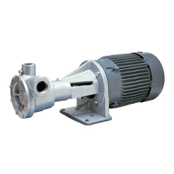
Regenerative Turbine Pumps
for LPG, NH
, and Many Other Liquefied Gases and Thin Liquids
3
All Models 10, 12, 13, 14, 16, 17, 18, and 19
C-Model
Warning: (1) Periodic inspection and maintenance of Corken products is essential. (2) Inspection, maintenance and installation of
Corken products must be made only by experienced, trained and qualified personnel. (3) Maintenance, use and installation of Corken
products must comply with Corken instructions, applicable laws and safety standards. (4) Transfer of toxic, dangerous, flammable or
explosive substances using Corken products is at user's risk and equipment should be operated only by qualified personnel according
to applicable laws and safety standards.
Scan QR code to view
maintenance video.
DL-Model
Solutions beyond products...
C-Model
F-Model-101
IF101Q
Advertisement
Table of Contents

Related Manuals for Corken F14


Summary of Contents for Corken F14
- Page 1 Warning: (1) Periodic inspection and maintenance of Corken products is essential. (2) Inspection, maintenance and installation of Corken products must be made only by experienced, trained and qualified personnel. (3) Maintenance, use and installation of Corken products must comply with Corken instructions, applicable laws and safety standards. (4) Transfer of toxic, dangerous, flammable or explosive substances using Corken products is at user’s risk and equipment should be operated only by qualified personnel according...
- Page 2 Corken One Year Warranty CORKEN, INC. warrants that its products will be free from defects in material and workmanship for a period of one year from date of installation, provided that the warranty shall not extend beyond twenty-four (24) months from the date of shipment from CORKEN.
-
Page 3: Table Of Contents
1.10 Wire Sizing Chart—C-Models........ -
Page 4: Principles Of A Regenerative Turbine Pump
• Corken provides two manual motor starters for models Differential pressure is the difference between the C10, C12, and C13. One is motor mounted and the pressure at the inlet and outlet of the pump. -
Page 5: The Inlet Should Include The Following
1. A bypass system for the pump must be installed. Without it, the pump has little chance of performing. C14, C16 2. A Corken B166 bypass valve allows the pump to vent DL10, DL12, DL13, DL14, DL16, DL17, DL18, vapors from the pump and act as a differential relief and DL19 valve making it ideal for the bypass system. -
Page 6: Coupling Alignment-F-Models
1 . 7 Coupling Alignment—F-Models 1 .8 Backup Wrench For a long service life, the coupling alignment must be To help prevent breaking the pump nozzle or springing near perfect. The shafts of the pump and driver are the pump out of alignment, always use a backup wrench carefully aligned at the factory but should always be as shown in figure 1.8. -
Page 7: Wire Sizing Chart-C-Models
1 . 1 0 Wire Sizing Chart—C-Models Minimum Wire Size, Approximate Heater AWG Length of Run Switch Motor Model Phase Voltage Full Load Element Wiring Connections Types Part No. in Feet Amperage Part No. 0–100 to 200 to 300 115V 208–230V... -
Page 8: Wire Sizing Chart-Dl- And F-Models
1 . 1 1 Wire Sizing Chart— more. If the motor overload protection device stops the motor during this period, this indicates the bypass valve DL- and F-Models is set too high and should be readjusted by turning the adjusting screw out until the motor can run constantly for this period of time. -
Page 9: Chapter 3-Preventative Maintenance
CAUTION: RELIEVE SYSTEM PRESSURE BEFORE PERFORMING ANY MAINTENANCE TO THE PUMP . • Use vapor eliminator valves and return to the vapor space of the tank. A Corken B166 bypass valve has ALL MAINTENANCE MUST BE PERFORMED IN this feature. -
Page 10: Chapter 5-Seal Replacement Instructions
C-models 10, 12, 13, 14, and 16. An electric motor can be wired to turn in a clockwise or The transfer of toxic, flammable, or explosive substances counterclockwise direction, so make sure it is wired to is always at the user’s risk. - Page 11 • The rear housing O-ring • The follower and follower O-ring that seals to the shaft • The impeller woodruff key • The seal locking pin • The seal clamp ring and 3 screws • One .002 red and one .003 green cover shim for adjusting impeller clearance 8.
- Page 12 as a result of over heating due to dry-running. This usually causes seal failure and excessive wear on the impeller. Since this impeller is not damaged and can be shimmed for proper clearance, it may be re-used. 10. Next, remove the impeller by pulling it off the shaft. If it does not slide off, insert one of the bolts used 12.
- Page 13 shaft until the locking pin is at the 6 o’clock position. Compress the seal assembly inwards until the pin should drops out. A light press with a screwdriver may help if the seal assembly does not move back. Pry the seal housing forward with the screwdriver and remove the housing from the pump.
- Page 14 20. Clean the inside and outside of the seal housing with a spray lubricant or light oil and set aside. Polish with 24. Before reassembling the pump, clean the mating emery paper if needed. surfaces on the front of the casing and the back of the cover.
- Page 15 Method 2 (For Buna-N, Neoprene , and Viton as shown in step 19 and reinstall using a plastic ® ® O-rings): This method does not require a seal locating handle screw driver or a ¾" PVC collar as shown. pin. When equipped with Buna-N, Neoprene , and Viton NOTE: This step applies to method 1 only.
- Page 16 Next, insert the O-ring and follower into the seal sleeve. 30. Next, install the seal clamp ring with three screws using the Phillips screwdriver. A magnetic screwdriver is helpful with this step. Install all three screws before tightening. Then tighten the screws evenly. DO NOT over tighten or break the screws.
- Page 17 Attach the pump cover and make sure the Corken name is level. Start with just four cover bolts and cross- tighten. Rotate the shaft by inserting a screwdriver in the fan guard and rotating the fan blade. If the shaft does not spin freely with one green shim, remove the cover and add the red shim for additional clearance.
-
Page 18: Model Number Identification Code And Available Options
Appendix A—Model Number Identification Code and Available Options C-Model (Close-Coupled) Regenerative Turbine Coro-Flo Pumps ® All Coro-Flo close-coupled pumps are listed by Underwriters’ Laboratories for LP-Gas ® Model Number Base Model # Base X X X X Inlet 1¼" NPT 1½"... - Page 19 Appendix A—Model Number Identification Code and Available Options DL-Model (Direct-Mount) Regenerative Turbine Coro-Flo Pumps ® Model Number Base Model # DL10 DL12 DL13 DL14 DL16 DL17 DL18 DL19 Base X X X X Inlet 1¼" NPT 1½" NPT 1½" NPT 1½" NPT 1¼" NPT 1¼" NPT 1½" NPT 1½" NPT Outlet 1"...
- Page 20 Appendix A—Model Number Identification Code and Available Options F-Model (Frame-Mount) Regenerative Turbine Coro-Flo Pumps ® Model Number Base Model # Base X X X X Inlet 1¼" NPT 1½" NPT 1½" NPT 1½" NPT 1¼" NPT 1¼" NPT 1½" NPT 1½" NPT Outlet 1"...
-
Page 21: Specifications
125 psig (8.6 bar)—C13 and C14 150 psig (10.3 bar)—C16 Driver range: 1 to 3 hp (0.75–2.2 kW) Temperature range: -25° to 225°F (-32° to 107°C) Flow range: 2–36 gpm (7.6–136.3 L/min) Material Specifications for C10, C12, C13, C14, and C16 Model Pumps Part... - Page 22 200 psig (13.8 bar)—all models 16, 17, 18, and 19 Optional driver range: 1 to 15 hp (0.75 to 11.2 kW) Temperature range: -25° to 225°F (-32° to 107°C) Flow range: 2–38 gpm (7.6–143.9 L/min) Maximum viscosity: 400 SSU (88 cSt)
-
Page 23: Performance
Capacity at 70 psid (5.2 bar d) 3 (11.4) C12 (60 Hz only) Service: Fill 20# cylinders in 15 to 30 seconds, 100# I.C.C. cylinders in 2 to 3 minutes, motor fueling through a meter at 15 gpm (56.8 L/min) Differential Pressure gpm (L/min) Capacity at 20 psid (1.4 bar d) - Page 24 Appendix C—Performance (Differential Pressure vs . Capacity) D-Model (Direct-Mount) and F-Model (Frame-Mount) Pumps All DL- and F-Model Pumps 2,880 RPM @ 50 Hz Model 14 Model 12 Model 10 Model 13 Capacity (L / min) 3,450 RPM @ 60 Hz...
- Page 25 Appendix C—Performance (Power Required vs . Capacity) D-Model (Direct-Mount) and F-Model (Frame-Mount) Pumps All DL- and F-Model Pumps 2,880 RPM @ 50 Hz Model 12 Model 14 Model 13 Model 10 Capacity (L /min) 3,450 RPM @ 60 Hz Model 12...
- Page 26 Appendix C—Performance (Differential Pressure vs . Capacity) Models 16 and 17 (C-, DL-, and F-Models) Model 16 Performance Curves 3,450 RPM at 60 Hz 2,880 RPM at 50 Hz L/min 3.00 2.25 1.50 0.75 Differential Pressure Model 17 Performance Curves...
- Page 27 Appendix C—Performance (Differential Pressure vs . Capacity) Models 18 and 19 (DL- and F-Models) Model 18 Performance Curves 3,450 RPM at 60 Hz 2,880 RPM at 50 Hz L/min 7.50 6.75 6.00 5.25 4.50 3.75 3.00 2.25 1.50 0.75 psid...
-
Page 28: Outline Dimensions
Appendix D—Outline Dimensions for C-Model (Close-Coupled) Pumps C10, C12, and C13 1 to 2 Hp Motors Outlet Inlet Motor starter optional Bolts Model Number Inlet Size Outlet Size Driver 1 hp (0.75 kW) 2 hp (1.5 kW) 1-1/4" NPT 1" NPT... - Page 29 Appendix D—Outline Dimensions for C-Model (Close-Coupled) Pumps C10, C12, C13, C14, and C16 3 Hp Motors (Single and Three Phase) Outlet Inlet Model Number Inlet Size Outlet Size Driver 3 hp (2.2 kW) C12, C13, C14 1-1/2" NPT 1" NPT...
- Page 30 4-5/16 14-3/32 (33.3) (109.5) (358.0) Outlet 1/4" NPT (50.8) 3/4" NPT Auxillary Discharge Port Inlet 10-3/8 2-5/16 (263.5) (58.7) CORKEN Diameter (228.6) Keyway 1.000 (25.40) 1/4 (6.4) 5-3/8 0.998 (25.35) (136.5) Bolt 5/16 (7.9) 3-7/8 3-7/8 8-3/64 4-5/8 (98.4) (98.4) (204.4)
- Page 31 Appendix D—Outline Dimensions for F-Model (Frame-Mount) Pumps F10, F12, F13, F14, F16, F17, F18, and F19 Model Pumps 4-5/16 12-13/16 (109.5) (325.4) 1-5/16 (33.3) Outlet (50.8) 3/4" NPT Auxillary Discharge Port Keyway Inlet (6.4) 8-1/2 2-5/16 (215.9) (58.7) 7-1/8 Bolt 5/16 (7.9) (181.0) Diameter 3-1/2...
- Page 32 -101 Mounting F10-101, F12-101, F13-101, F14-101, F16-101, F17-101, F18-101, and F19-101 Model Pumps 1/4" Auxiliary B (outlet) discharge 3/4 NPT A (inlet) CORKEN Four bolts, 1/2" diameter Flange Dimensions Model A (inlet) B (outlet) F10, F16, and F17 1-1/4" NPT 1"...
- Page 33 Appendix D—Outline Dimensions for F-Models (Frame-Mount) Pumps with -103 Mounting F10-103, F12-103, F13-103, F14-103, F16-103, F17-103, F18-103, and F19-103 Model Pumps B (outlet) A (inlet) Belt guard 3/4" NPT 1/4" Adjusting base Four bolts, 1/2" diameter Flange Dimensions Model A (inlet) B (outlet) F10, F16, and F17 1-1/4"...
-
Page 34: Parts Details
Appendix E—Parts Details for All C-Model (Close-Coupled) Pumps C10, C12, C13, C14, and C16 CAUTION: Always relieve pressure in the unit before attempting any repairs. WARNING Part No . Description Qty . Part No . Description Qty . No . - Page 35 Appendix E—Parts Details for All DL-Model (Direct-Mount) Pumps DL10, DL12, DL13, DL14, DL16, DL17, DL18, and DL19 CAUTION: Always relieve pressure in the unit before attempting any repairs. WARNING Part No . Description Qty . Part No . Description Qty . No .
- Page 36 Phillips head screw 6-32 x 1/4" 1014-1 Case clearance shim (0.003—green) As req. 5002-281 Bearing retainer ring 2-246_ Case O-ring (non-PTFE) 1238 Bearing cap a, c 2-247E Case O-ring PTFE 1006 Grease seal 1003-0 Impeller (bronze standard)—model 10 5102-118 Bearing retainer ring 1003-2 Impeller (bronze standard)—model 12...
- Page 37 2343-X Coro-seal (not shown) d, g Assembly No . Assembly Name 2738 Rotor c, f Seal assembly with 1007-X, 1008, 1009, 1014, 1014-1, 2738-1 Rotor for Coro-Seal d, g 113-CX_6 a, d 1080, 2497, 2736, 2737, 2739-X, 2-018, 2-224, 2-246...
- Page 38 Appendix E—Parts Details for the F-Model Pump Coupling Guard All F- and FF-Models (Pump Sizes 10, 12, 13, 14, 16, 17, 18, and 19) 7003-010NC050B 2800 coupling guard Coupling Motor Pump Coupling spider 7101-010WL06B CAUTION: The power supply to the motor must be disconnected before working on the pump drive system.
- Page 39 Appendix E—Parts Details for the C-Model Pump Starter Box Motor Mounted Model (2277-X1) Attach ground wire here Use original switch screws Surface atness: When assembled with cover 2277 1, 2 1, 2 a .0015 feeler gauge will not enter the joint more than 1/8".
- Page 40 Appendix E—Parts Details for the C-Model Pumps Starter Box Wall Mounted Model (2277-X2) Attach ground wire here Use original switch screws Surface atness: When assembled with cover 2277 1, 2 1, 2 a .0015 feeler gauge will not enter the joint more than 1/8".
-
Page 41: Troubleshooting Guide
Appendix F—Troubleshooting Guide In diagnosing pump and “system” troubles, the following information is essential: 1. Pump model and serial number 6. Pressure at pump’s discharge port 2. Electric motor: hp and RPM 7. Pressure in the storage tank 3. Product specific gravity 8. -
Page 42: Extended Storage
Symptom Probable Cause Remedy Noise or Defective or wrong size Confirm the size of the bypass valve required for the application. vibration in bypass valve Inspect, repair, or replace the valve. the pump Loose anchor bolts Tighten all pump’s anchor bolts. (continued) Electric motor High differential pressure... -
Page 43: Aboveground Installation/Piping Instructions
Appendix H—Aboveground Installation/Piping Instructions Yes! Use inlet line larger than pump Don’t use restricted inlet line! suction nozzle. Same size nozzle OK on short runs. Pressure drop caused by restriction in suction line will cause vaporization and cavitation. Yes! Concentric Reducer Eccentric Reducer An eccentric reducer should always be used when reducing into any pump inlet where vapor might be encountered in the pumpage. - Page 44 Appendix H—Aboveground Installation/Piping Instructions Never locate pump above level Yes! of liquid feeding pump. Product must be able to flow by gravity into pump. Always locate pump below tank level ...the lower the better! Since liquefied gases boil when drawn into a pump by its own suction, the pump must be fed by gravity flow to give stable, trouble-free operation.
- Page 48 Solutions beyond products... CORKEN, INC. • A Unit of IDEX Corporation 9201 North I-35 Service Road, Oklahoma City, OK. 73131 Phone (405) 946-5576 • Fax (405) 948-7343 Website: www.corken.com E-mail: cocsalesdept@idexcorp.com @CorkenInc Printed in the U.S.A. March 2020...
Need help?
Do you have a question about the F14 and is the answer not in the manual?
Questions and answers