Table of Contents
Advertisement
ORIGINAL INSTRUCTIONS
Installation, Operation
& Maintenance Manual
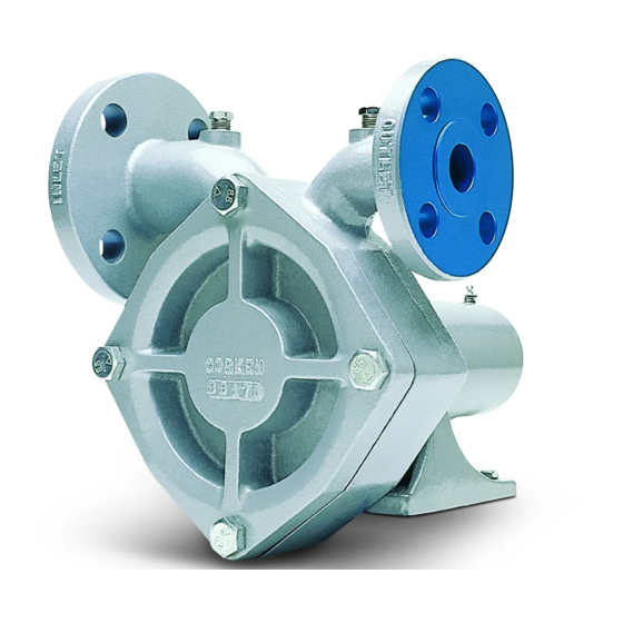
Regenerative Turbine Pumps
for LPG, NH
, and Many Other Liquefied Gases and Thin Liquids
3
All Models 060, 075, and 150
Warning: (1) Periodic inspection and maintenance of Corken products is essential. (2) Inspection, maintenance and installation of
Corken products must be made only by experienced, trained and qualified personnel. (3) Maintenance, use and installation of Corken
products must comply with Corken instructions, applicable laws and safety standards. (4) Transfer of toxic, dangerous, flammable or
explosive substances using Corken products is at user's risk and equipment should be operated only by qualified personnel according
to applicable laws and safety standards.
Scan QR code to view list
of maintenance videos.
Frame Mount
ASME Class 300 RF (ANSI) Flange (FF) and DIN Flange (FD)
Direct Mount
ASME Class 300 RF (ANSI) Flange (DLF) and DIN Flange (DLD)
Solutions beyond products...
IF102H
Advertisement
Table of Contents

Related Manuals for Corken Coro-Flo DLD150


Summarization of Contents
Chapter 1-Installation
1.1 Location Requirements
Specifies requirements for pump installation location and ventilation.
1.2 Inlet Piping Requirements
Details essential components for the pump inlet piping system.
1.3 Outlet Piping Requirements
Lists required components for the pump outlet piping.
1.4 Bypass System Requirements
Outlines mandatory components for the pump bypass system.
1.5 Pump Foundation for Frame Mounted Models
Provides guidance on constructing a foundation for frame-mounted pumps.
1.6 Level Base Installation
Describes how to ensure the pump mounting base is level.
1.7 Coupling Alignment
Explains the importance and method for aligning pump and driver couplings.
1.8 Driver Installation and Wiring
Covers critical aspects of correctly wiring and installing the electric motor driver.
1.9 Wire Sizing Chart
Provides a chart for selecting appropriate wire sizes based on motor HP and distance.
Chapter 2-Operation
2.1 Filling New Cylinders and Tanks
Details the procedure for filling new tanks and cylinders with gas.
2.2 Pumping From Underground Tanks
Discusses challenges and considerations for pumping liquefied gases from underground tanks.
Chapter 3-Preventative Maintenance
Purpose, Scope, and Procedures
Combines explanations of maintenance purpose, scope, and general safe procedures.
Visual Inspection and Strainer Cleaning
Details visual checks for leaks/damage and the process for cleaning the inlet strainer.
Component Inspection and Lubrication
Covers inspection of couplings, bearings, and starter points, plus lubrication tasks.
Performance Testing and Bolt Tightening
Explains pump performance testing and the importance of checking hold-down bolts.
Chapter 4-Repair Service
Impeller and Mechanical Seal Repairs
Covers common repairs involving the pump's impeller and mechanical seal.
Chapter 5-Seal Replacement Instructions
Disassembly and Component Removal
Details steps for disassembling the pump and removing its components.
Seal Cleanliness and Workmanship
Emphasizes the importance of cleanliness and careful handling during seal replacement.
Seal Housing and Seat Procedures
Covers removal of the seal housing O-ring, inspection of bearings, and seal seat removal.
Seal Assembly and Installation
Guides on verifying new seals and installing the seal housing and O-ring.
Shaft Components and Final Assembly
Details installation of seal sleeve O-ring, seal, and retainer ring.
Impeller, Key, and Cover Installation
Explains the installation of the impeller, key, and pump cover.
Appendix A-Model Number Identification Code
Model 060 Coro-Flo
Pump Options
Breaks down model number codes and available options for the Model 060.
Model 075 Coro-Flo
Pump Options
Breaks down model number codes and available options for the Model 075.
Model 150 Coro-Flo
Pump Options
Breaks down model number codes and available options for the Model 150.
Appendix B-Material and Mechanical Specifications
Equipment Type and Options Overview
Categorizes pump types and available options for models 060, 075, 150.
Features and Benefits Summary
Highlights key advantages and characteristics of the Coro-Flo pumps.
Operating Specifications and Limits
Provides operational parameters like pressure, flow, and temperature limits.
Pump Component Material Specifications
Details the materials used for various pump components.
Appendix C-Performance Curves
Model 060 Coro-Flo
Performance Curves
Shows performance curves specific to the Model 060 pump.
Model 075 Coro-Flo
Performance Curves
Displays performance curves for the Model 075 pump.
Model 150 Coro-Flo
Performance Curves
Provides performance curves for the Model 150 pump.
Appendix D-Outline Dimensions
Frame Mount Dimensions
Presents dimensional drawings and specifications for frame mount pump configurations.
Direct Mount Dimensions
Shows dimensional drawings and specifications for direct mount pump configurations.
Frame Mount Dimensions with
–101 Mounting
Details dimensions for frame mount models with a specific mounting type.
Appendix E-Parts Details
Frame Mount Parts List
Lists and illustrates pump components with part numbers for frame mount models.
Direct Mount Parts List
Lists and illustrates pump components with part numbers for direct mount models.
Appendix F-Troubleshooting Guide
Low Capacity Issues
Addresses issues related to reduced pump output and probable causes.
No Flow or Locked Pump
Provides causes and remedies for pumps with no flow or that are locked.
Pump Pressure Issues
Offers solutions for pumps failing to generate sufficient pressure.
Noise and Vibration Causes
Explains common causes of noise and vibration and their fixes.
Motor Overheating and Leaks
Troubleshoots motor overheating, overload protection, and leaks.
Appendix H-Installation and Piping Instructions
Aboveground Inlet Piping and Reducer Guidelines
Covers inlet piping, reducer types, and avoiding restrictions for aboveground pumps.
Aboveground Bypass Line Configuration and Routing
Details correct configuration and routing for bypass lines in aboveground systems.
Aboveground Pump Location Relative to Tank Level
Provides guidance on optimal pump placement relative to the tank level.
Aboveground Back Check Valve and Bypass Valve Usage
Explains the use of back check valves and bypass valve types for aboveground systems.
Aboveground Upstream Straight Pipe Requirement
Specifies the recommended length of straight pipe upstream of the pump.
Aboveground Bypass Valve Configuration for Vaporizers
Details bypass valve configurations for vaporizer feed systems.
Underground Installation Overview
Introduces considerations for installing pumps in underground tank systems.
Underground Submersible Manifold Use
Discusses the use of submersible manifolds in underground pump installations.
Need help?
Do you have a question about the Coro-Flo DLD150 and is the answer not in the manual?
Questions and answers