Table of Contents
Advertisement
Quick Links
ORIGINAL INSTRUCTIONS
IF101K
Installation, Operation
& Maintenance Manual
Regenerative Turbine Coro-Flo
Pumps
®
Models C, CF, DL, DLF, DS, DSF, F, and FF
Pump Sizes 9, 10, 12, 13, 14, and 15
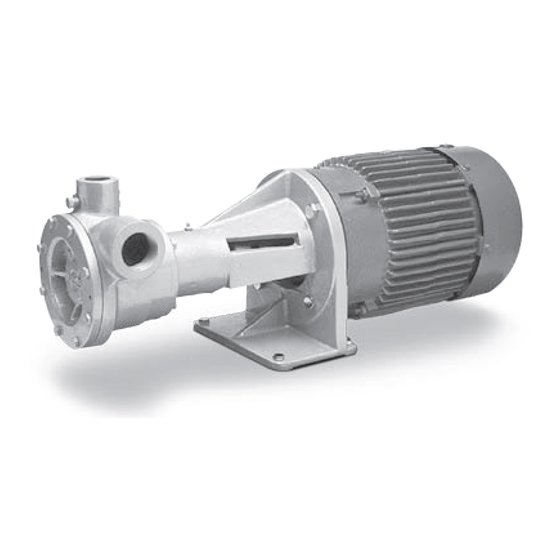
DS-/DL-Model
C-Model
C-Model
F-Model
Warning: (1) Periodic inspection and maintenance of Corken products is essential. (2) Inspection, maintenance and installation of Corken products must be made only by
experienced, trained and qualified personnel. (3) Maintenance, use and installation of Corken products must comply with Corken instructions, applicable laws and safety
standards (such as NFPA Pamphlet 58 for LP-Gas and ANSI K61.1-1972 for Anhydrous Ammonia). (4) Transfer of toxic, dangerous, flammable or explosive substances
using Corken products is at user's risk and equipment should be operated only by qualified personnel according to applicable laws and safety standards.
Solutions beyond products...
www.northridgepumps.com
Advertisement
Table of Contents

Related Manuals for Corken Coro-Flo 9 Series


Summary of Contents for Corken Coro-Flo 9 Series
- Page 1 F-Model Warning: (1) Periodic inspection and maintenance of Corken products is essential. (2) Inspection, maintenance and installation of Corken products must be made only by experienced, trained and qualified personnel. (3) Maintenance, use and installation of Corken products must comply with Corken instructions, applicable laws and safety standards (such as NFPA Pamphlet 58 for LP-Gas and ANSI K61.1-1972 for Anhydrous Ammonia).
- Page 2 Corken One Year Limited Warranty Corken, Inc. warrants that its products will be free from defects in material and workmanship for a period of one year from date of installation, provided that the warranty shall not extend beyond twenty-four (24) months from the date of shipment from Corken.
-
Page 3: Table Of Contents
® CHAPTER 1—INSTALLATION OF YOUR CORKEN CORO-FLO PUMP ....... . . 5 1.1 Location . -
Page 4: Principles Of A Regenerative Turbine Coro-Flo ® Pump
The C14 motor is three-phase, 60 Hertz, 3450 RPM, pressure is the difference between the pressure at the 230/460 bolts. Corken provides two manual motor inlet of the pump and at the outlet of the pump. starters for models C10, C12 and C13. One is motor- mounted and the other is wall-mounted. -
Page 5: Chapter 1-Installation Of Your Corken Coro-Flo ® Pump
1. The pump bypass system must be installed. Without this system, the pump has little chance of performing. 2. A Corken B166 bypass valve (a special valve to vent the pump of vapors and to act as a differential relief valve) makes the ideal installation. -
Page 6: Pump Foundation-F-Models
1.5 Pump Foundation—F-Models If misalignment exists, adjust the shims between the pump base and the foundation until exact alignment is accomplished. Every pump deserves a firm, neat concrete foundation (see figure 1.5). There are many ways to construct a foundation, 1.8 Back-up Wrench and the example in figure 1.5 is only a suggestion. -
Page 7: Wire Sizing Chart-C-Models
1.10 Wire Sizing Chart—C-Models Minimum Wire Size, Approximate Heater Switch Motor AWG Length of Run Model Phase Voltage Full Load Element Wiring Connections Types Part No. in Feet Amperage Part No. 0–100 to 200 to 300 115V 208–230V 2277-X1 or 2277-X2 Switch Assy 2277-X1 or 2277-X2 Switch Assy S-10 2555... -
Page 8: Wire Sizing Chart-Dl-, Dlf-, Ds-, Dsf-, F-, And Ff-Models
1.11 Wire Sizing Chart—DL-, DLF-, DS-, pressure. Lock the lock nut, and permit the pump to circulate liquid for a half hour or more. If the motor DSF-, F-, and FF-Models overload protection device stops the motor during this period, this indicates the bypass system valve is set too Motor Recommended wire size, AWG high and should be readjusted by turning the adjusting... -
Page 9: Installation Design Criteria For Underground Tank Applications
“efficiency” test before any attempt is made to repair • Use vapor eliminator valves (Corken B166 by-pass it. The trouble may lie in the piping system rather than valves have this feature) in the pump. -
Page 10: Chapter 5-Coro-Flo ® Seal Replacement Instruction
Inspection, maintenance, and installation of the pump must be performed by trained personnel. All procedures must comply with the Corken Installation, Operation & Maintenance manual, applicable local codes and safety standards. The transfer of toxic, flammable, or explosive substances is always at the user’s risk. - Page 11 • The case cover O-ring • The rear housing O-ring • The follower and follower O-ring that seals to the shaft • The impeller woodruff key • The seal locking pin • The seal clamp ring and 3 screws • And, a .002 red and .003 green cover shim for adjusting impeller clearance 8.
- Page 12 cause of seal failure and excessive impeller wear. This impeller is not damaged. As long as it can be shimmed for proper clearance, the impeller may be re-used. 10. Next, remove the impeller by pulling it off the shaft. If it is stuck, insert an existing bolt from the pump cover 12.
- Page 13 the shaft so the locking pin is in the 6 o’clock position. Compress the seal assembly with your thumbs and the pin should drop out. A light press with a screwdriver may help if the seal assembly does not move back. Pry the seal housing forward with the screwdriver and remove the housing from the pump.
- Page 14 20. Clean the inside and outside of the seal housing with a spray lubricant or light oil and set aside. Polish with 24. Before you reassemble the pump, now is a good time emery paper if needed. to clean the front of the casing and the back of the cover mating surfaces.
- Page 15 There is a locating pin in the back of the seal housing that must align with the notch in the back of the seal seat. To aid the installation process and prevent damage to 27. Reinstall all the metal shims, that were removed during the seal seat, we recommend using a plastic handle disassembly, behind the flange of the seal housing.
- Page 16 Next, insert the follower O-ring and the follower into the seal sleeve. 30. Next, install the seal clamp ring with three screws using the Phillips screwdriver. A magnetic screwdriver is helpful if available. Install all three screws before tightening. Then tighten the screws evenly. Do not over tighten or break the screws.
- Page 17 Attach the pump cover making sure the Corken name is level with the casing and cross-tighten with four of the cover bolts. Rotate the shaft by inserting a screwdriver in the fan guard and rotating the fan blade. If the shaft does not spin freely with one green shim, add the red shim for additional clearance.
-
Page 18: Model Number Identification Code And Available Options
Appendix A—Model Number Identification Code and Available Options C-Model (Close-Coupled) Regenerative Turbine Coro-Flo Pumps ® C-MODEL REGENERATIVE TURBINE PUMPS (CLOSE-COUPLED) All Coro-Flo® close-coupled pumps are listed by Underwriters' Laboratories for LP Gas. MODEL NUMBER BASE MODEL # CF10 CF12 CF13 CF14 1½"... - Page 19 Appendix A—Model Number Identification Code and Available Options D-Model (Direct-Mount) Regenerative Turbine Coro-Flo Pumps ® D-MODEL REGENERATIVE TURBINE PUMPS (DIRECT MOUNTED) DS models connect to motor frame size 56C through 145TC. DL models connect to motor frame size 182TC through 215TC. All standard ANSI port sizes are 300 lb.
- Page 20 Appendix A—Model Number Identification Code and Available Options F-Model (Frame-Mount) Regenerative Turbine Coro-Flo Pumps ® F-MODEL REGENERATIVE TURBINE PUMPS (FRAME MOUNTED) MODEL NUMBER BASE MODEL NUMBER (NPT) BASE X Inlet 1¼" NPT 1¼" NPT 1½" NPT 1½" NPT 1½" NPT 1½"...
-
Page 21: Specifications
Appendix B—Specifications for All C-Model (Close-Coupled) Pumps Operating Specifications for C10, C12, C13, C14, CF10, CF12, CF13, and CF14 Model Pumps Inlet: C10: 1-1/4" NPT, C12 through C14: 1-1/2" NPT, 300# ANSI optional Outlet: 1" NPT, 300# ANSI optional RPM: 3450 @ 60 Hz, limited use in 50 Hz @ 2880 RPM Maximum working pressure: 400 psig (27.6 bar) - Page 22 Appendix B—Specifications for All D-Model (Direct-Mount) and F-Model (Frame-Mount) Pumps Operating Specifications for DL-, DLF-, DS-, DSF-, F-, and FF-Model Pumps Inlet: F/DS/DL 9 through 10, 1-1/4" NPT Maximum working pressure: 400 psig (27.6 bar) F/DS/DL 12 through 14, 1-1/2" NPT Maximum differential pressure: 125 psig (8.6 bar) Optional: 1"...
- Page 23 Appendix C—Performance for C-Model (Close-Coupled) Pumps C10 (60 Hz only) Service: Fill 20# cylinders in 30 seconds to 1 minute, 100# cylinders in 2-1/2 to 3-1/2 minutes, motor fueling through a meter at 7 gpm (26.5 L/min) Differential Pressure gpm (L/min) Capacity at 20 psid (1.4 bar d) 12 (45.4) Capacity at 50 psid (3.4 bar d)
-
Page 24: Performance
Appendix C—Performance (Differential Pressure vs. Capacity) D-Model (Direct-Mount) and F-Model (Frame-Mount) Pumps All DL-, DLF-, DS-, DSF-, F-, and FF-Model Pumps 2880 RPM @ 50 Hz Model 15 Model 14 Model 10 Model 13 Model 12 Capacity (L / min) 3450 RPM @ 60 Hz Model 14 Model 12... - Page 25 Appendix C—Performance (Power Required vs. Capacity) D-Model (Direct-Mount) and F-Model (Frame-Mount) Pumps All DL-, DLF-, DS-, DSF-, F-, and FF-Model Pumps 2880 RPM @ 50 Hz Model 12 Model 15 Model 14 Model 10 Model 13 Capacity (L / min) 3450 RPM @ 60 Hz Model 15 Model 14...
-
Page 26: Outline Dimensions
Appendix D—Outline Dimensions for C-Model (Close-Coupled) Pumps C10, C12, C13, and C14 1 to 2 Hp Motors Driver 3/4 hp (0.56 kW) 1 hp (0.75 kW) 2 hp (1.5 kW) Motor part number 2555 2556 4261 Outline Dimensions for Pumps with Obsolete Bluffton Motors—Inches (Centimeters) Model hp C10, 17-1/8... - Page 27 Auxilliary Models DL12, DL13, DL14, DL15 = 1-1/2 NPT B (outlet) discharge 1" NPT 3/4" NPT 1/4 NPT CORKEN 1/4 (0.64) Keyway Notes: Bolt circle diameter is 7-1/4 Rabbet diameter is 8-1/2" 182TC to 256TC frame motors (bolts) Motor mounting bolts are 1/2-13 x 1-1/4" H.H.
- Page 28 1-1/2 ANSI 300# flange B (outlet) Auxilliary 1" ANSI 300# flange discharge 3/4" NPT 1/4" CORKEN 1/4 (0.64) Keyway Notes: Bolt circle diameter 7-1/4" Rabbet diameter 8-1/2" 182TC to 256TC frame motors (bolts) Motor mounting bolts are 1/2-13 x 1-1/4" H.H.
- Page 29 Models DS9, DS10 = 1-1/4 NPT 1.000 (2.540) Models DS12, DS13, DS14, DS15 = 1-1/2 NPT 0.998 (2.535) Auxiliary discharge B (outlet) 3/4" NPT 1/4" CORKEN 1/4" (0.64) Keyway Notes: Bolt circle diameter is 5-7/8" Rabbet diameter is 4-1/2" (bolts) Up to 145TC frame motors Motor mounting bolts are 3/8-16 x 1"...
- Page 30 Auxilliary 0.998 (2.535) 1" ANSI 300# flange discharge 3/4" NPT 1/4 NPT 1/4 NPT CORKEN 1/4 (0.64) Keyway Notes: Bolt circle diameter is 5-7/8" Rabbet diameter is 4-1/2" Up to 145TC frame motors (bolts) Motor mounting bolts are 3/8-16 x 1" H.H.
- Page 31 Appendix D—Outline Dimensions for F-Model (Frame-Mount) Pumps All F9, F10, F12, F13, F14, and F15 Model Pumps A (inlet) Models F9, F10 = 1-1/4 B (outlet) Models F12, F13, F14, F15 = 1-1/2 3/4" NPT Diameter 1.000 (2.540) 0.998 (2.535) 1/4 (0.64) Keyway (bolts) Flange Dimensions...
- Page 32 1" ANSI 300# flange 1-1/2 ANSI 300# flange 1/4" Auxiliary 1/4" discharge 3/4 NPT Diameter 1.000 (2.540) 0.998 (2.535) CORKEN (bolts) Flange Dimensions Model A (inlet) B (outlet) FF9–FF15 1-1/2" 300# ANSI 1" 300# ANSI FF9–FF15 300# ANSI Outline Dimensions—Inches (Centimeters)
- Page 33 All F9-101, F10-101, F12-101, F13-101, F14-101, and F15-101 Model Pumps B (outlet) A (inlet) 1" NPT F9-F10 = 1-1/4" NPT Auxiliary F12-F15 = 1-1/2 NPT discharge 1/4" 3/4 NPT CORKEN Four bolts, 1/2" diameter Flange Dimensions Model A (inlet) B (outlet) F9–F10 1-1/4" NPT 1" NPT F12–F15...
- Page 34 Appendix D—Outline Dimensions for F-Models (Frame-Mount) Pumps with -103 Mounting All F9-103, F10-103, F12-103, F13-103, F14-103, and F15-103 Model Pumps A (inlet) B (outlet) F9-F10: 1-1/4" NPT 1" NPT F12-F15: 1-1/2" NPT Belt guard 3/4" NPT 1/4" Adjusting base Four bolts, 1/2" diameter Flange Dimensions Model A (inlet)
-
Page 35: Parts Details
Appendix E—Parts Details for All C-Model (Close-Coupled) Pumps C10, C12, C13, and C14 CAUTION: Always relieve pressure in the unit before attempting any repairs. WARNING Bill of Materials Part No. Description Qty. Part No. Description Qty. 7001-031NC100A Hex head cap screw 1914-1 Nameplate 1001-0... - Page 36 Appendix E—Parts Details for All D-Model (Direct-Mounted) Pumps This includes DL-, DLF-, DS-, DSF-models in sizes 9, 10, 12, 13, 14, & 15 CAUTION: Always relieve pressure in the unit before attempting any repairs. WARNING Part No. Description Qty. Part No. Description Qty.
- Page 37 Appendix E—Parts Details for All F-Model (Frame-Mounted) Pumps This includes F- and FF-models in sizes 9, 10, 12, 13, 14, & 15 CAUTION: Always relieve pressure in the unit before attempting any repairs. WARNING Part No. Description Qty. Part No. Description Qty.
- Page 38 Appendix E—Parts Details for the Balanced Seal Assembly (113-CX_) All C-, DS-, DSF-, DL-, DLF-, F-, FF-Models (Sizes 9, 10, 12, 13, 14, & 15) CAUTION: Always relieve pressure in the unit before attempting any repairs. WARNING Part No. Description Qty.
- Page 39 Appendix E—Parts Details for the F-Model Pump Coupling Guard All F- and FF-Models (Pump Sizes 9, 10, 12, 13, 14, and 15) CAUTION: The power supply to the motor must be disconnected before working on the pump drive system. WARNING Part No.
- Page 40 WARNING the supply circuit before opening. Keep assembly tightly closed when in operation. Specify maximum motor amperage for proper heating selection. Section A For current Corken Coro-Flo C-Model motors the following heaters Part No. Description Qty. are standard. 2275 Switch: 3/4 hp – 1 hp Motor No.
- Page 41 Specify maximum motor amperage for proper heating selection. Section A NOTE: The original instructions that come with the switch are For current Corken Coro-Flo C-Model motors the following heaters Part No. Description Qty. placed inside the box. are standard.
- Page 42 Appendix E—Parts Details for New Part Interference Dimensions for Coro-Flo Pumps All Models ® Cover Impeller Model A (maximum) B (maximum) C (maximum) 1.489 0.142 4.126 D 1.489 0.142 4.126 D 1.398 0.208 4.062 D 1.388 0.227 4.374 D 1.351 0.301 4.374 D 1.398...
-
Page 43: Troubleshooting Guide
Appendix F—Troubleshooting Guide In diagnosing pump and “system” troubles, the following information is essential: 1. Pump model and serial number 6. Pressure at pump’s discharge port 2. Electric motor; hp and RPM 7. Pressure in the storage tank 3. Product specific gravity 8. -
Page 44: Extended Storage
Symptom Probable Cause Remedy Noise or Defective or wrong size Confirm the size of the by-pass valve required for your application. vibration in the By-pass valve Inspect, repair or replace the valve. pump (continued) Loose anchor bolts Tighten all pump’s anchor bolts. Electric motor High differential pressure Check the motor’s full load amperage. -
Page 45: Aboveground Installation/Piping Instructions
Appendix H—Aboveground Installation/Piping Instructions Yes! Use inlet line larger than Don’t use restricted inlet line! pump suction nozzle. Same size nozzle OK on short runs. Pressure drop caused by restriction in suction line will cause vaporization and cavitation. Yes! Concentric Reducer Eccentric Reducer An eccentric reducer should always be used when reducing into any pump inlet where vapor might be encountered in the pumpage. - Page 46 Appendix H—Aboveground Installation/Piping Instructions Yes! Never locate pump above level of liquid feeding pump. Product must be able to flow by gravity into pump. Always locate pump below tank level ...the lower the better! Since liquefied gases boil when drawn into a pump by its own suction, the pump must be fed by gravity flow to give stable, trouble-free operation.
-
Page 47: Underground Installation/Piping Instructions
Appendix I—Underground Piping Diagram 5 feet (1,524 mm) maximum Approximately 14 feet (4,267 mm) maximum Underground tank Minimum liquid level of 12 inches (304 mm) above end of dip tube www.northridgepumps.com... - Page 48 NFPA 58 for LP-Gas and ANSI K6.1-1972 for Anhydrous Ammonia. 5.0 Transfer of toxic, dangerous, flammable or explosive substances using Corken equipment is at the user’s risk. Only qualified personnel should operate Corken equipment according to the applicable laws and safety standards.
Need help?
Do you have a question about the Coro-Flo 9 Series and is the answer not in the manual?
Questions and answers