Table of Contents
Advertisement
Advertisement
Table of Contents

Related Manuals for Vermes MDV 3200A


Summary of Contents for Vermes MDV 3200A
- Page 1 Manual Micro Dispensing System MDS 3010A-FD MDS 3020A-FD With switch mode functionality Manual Revision 6.0 (Please notice that pictures in this manual might differ from actual delivery status on the system.) Manual MicroDispensingSystems MDS3010A-FD and MDS 3020A-FD VTK-TS-MA-032 Revision A...
-
Page 2: Table Of Contents
User Manual MicroDispensing Systems MDS 3010A-FD and MDS 3020A-FD Table of Contents 1. Introduction ............................1 1.1. General Information ......................... 1 1.2. Areas of applications ........................1 1.3. Machining ............................2 1.4. Product line MDS 3000 ........................2 1.5. Compatibility with earlier product lines....................3 1.6. - Page 3 User Manual MicroDispensing Systems MDS 3010A-FD and MDS 3020A-FD 6.5.4. Handling Error 501 Valve Defect ....................35 6.5.5. PLC-interface: Sub-D, 15-pin ..................... 36 6.6. Control options ..........................38 6.7. Remote Adjust ..........................39 6.8. Delay times ............................ 41 6.8.1. PLC Trigger Delay ........................41 7.
-
Page 4: Introduction
1. Introduction 1.1. General Information By buying a Vermes Microdispensing System of the MDS 3000 family you receive a high-quality system manufactured with greatest care. In this manual you will in general become acquainted with Vermes Microdispensing services and in detail with the use of your system. -
Page 5: Machining
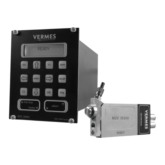
(MDX series). Figure 1: MicroDispensing System MDS 3000 To cover a wide range of viscosity Vermes Microdispensing developed three different types of valves, which can be used depending on the viscosity of the media. MDV 3010A: for low viscous fluids (water-like fluids) MDV 3020A: for low and medium viscous fluids (e.g. -
Page 6: Compatibility With Earlier Product Lines
User Manual MicroDispensing Systems MDS 3010A-FD and MDS 3020A-FD 1.5. Compatibility with earlier product lines This manual describes the handling of MicroDispensing Systems 3010A and 3020A. This product line is characterized by a series of additional functions. AutoID: The calibration data are recorded by a memory chip. The valve logs in automatically into the control unit MDC 3090A. -
Page 7: Important Information
The offered safety by the apparatus can be affected by using parts/units not advised by VERMES MICRODISPENSING. The same is true for the usage of dangerous substances or the operation in an explosive environment, for which the MicroDispensing System MDS 3010A/MDS 3020A is not designed. -
Page 8: Safety Instructions
User Manual MicroDispensing Systems MDS 3010A-FD and MDS 3020A-FD 2.4. Safety instructions Check whether all fluid box connections are attached and sealed. Attention!!! Make sure all connections and connectors are mounted according to instructions and all components are specified for use with the intended pressure. -
Page 9: Dispensing Medium
User Manual MicroDispensing Systems MDS 3010A-FD and MDS 3020A-FD 2.6. Dispensing medium Before filling up the fluid box system with aggressive fluids, make sure that all parts contacting the fluid are resistant against it. In case of doubt please consult our Customer Support. -
Page 10: Adjust And First Drop
User Manual MicroDispensing Systems MDS 3010A-FD and MDS 3020A-FD 3. Adjust and First Drop Before you can operate with the system, you have to choose in which operation mode you would like to use the system. 3.1. Definition The adjust process can be used to get a precise calibration of the valve stroke and therefore to get a standardization between different systems. -
Page 11: Operation Mode Select
User Manual MicroDispensing Systems MDS 3010A-FD and MDS 3020A-FD 3.3. Operation Mode Select To select the mode of operation follow the instructions below: Switch on the Control Press enter Unit: The display button. The display shows the message: is showing the main menu. -
Page 12: Adjust First Drop
User Manual MicroDispensing Systems MDS 3010A-FD and MDS 3020A-FD Use the escape button The status of the to exit the menu. operation mode is shown on the start screen. READY TNLmax = XX% means: You are using the First Drop mode. - Page 13 User Manual MicroDispensing Systems MDS 3010A-FD and MDS 3020A-FD The display shows the The display shows message: the message: ENTER FOR Calibration 500 SHOTS please wait Confirm with the enter The calibration can button. take a few minutes. Please wait.
-
Page 14: Positioning Of The First Drop
User Manual MicroDispensing Systems MDS 3010A-FD and MDS 3020A-FD 3.5. Positioning of the First Drop To adjust the First The display shows Drop, press the F2 the message: button. FILL UP WITH MEDIUM!!!!! Mount the cartridge Confirm the message with the dispense... - Page 15 User Manual MicroDispensing Systems MDS 3010A-FD and MDS 3020A-FD To confirm the The display shows message CLEAN the message for the NOZZLE press the adjustment of the enter button. Needle Lift setting. The Needle Lift (in %) describes at which...
-
Page 16: Adjust Normal Mode
User Manual MicroDispensing Systems MDS 3010A-FD and MDS 3020A-FD 3.6. Adjust Normal Mode Switch on the Control Press the adj button Unit. The display to start the adjust. shows the message: READY The red LED for the First Drop indication is... -
Page 17: Notice For The Adjust And The Performing Of The First Drop
User Manual MicroDispensing Systems MDS 3010A-FD and MDS 3020A-FD Consider the value on If you have reached the screen while the required value, adjusting the nut. confirm the message: In the allowed range ENTER IF GREEN the green LED XX µm (adjusted) is on. -
Page 18: Scope Of Supply
User Manual MicroDispensing Systems MDS 3010A-FD and MDS 3020A-FD 4. Scope of Supply Check after receipt of your MicroDispensing System, if the delivery is complete. 4.1. Standard Check after receipt for sufficiency. The following components are part of the standard scope of supply for the MDS 3000 family:... -
Page 19: Microdispensing Valve Mdv 3010A And Mdv 3020A
Actuator system The actuator system is the heart of the MicroDispensing Valves of Vermes Microdispensing. It contains the sensor (regulated valves), the piezo actuator and the mechanics for the tappet drive. The housing and the mechanics are encapsulated to avoid contamination and intrusion of humidity. -
Page 20: Technical Data Mdv 3010A/3020A
User Manual MicroDispensing Systems MDS 3010A-FD and MDS 3020A-FD 5.2. Technical data MDV 3010A/3020A Property Value Unit/Explanation Dispensing quantity range from 9 nl per cycle Supply air pressure range 0.1 to 7 bar (relative) (0,1 – 73 psi) Dynamic viscosity of dispense media... -
Page 21: Null-Set Dispensing
User Manual MicroDispensing Systems MDS 3010A-FD and MDS 3020A-FD 5.4.3. Null-set dispensing Dispensing without medium (inflow disconnected) leads to upper wear, mainly of the nozzle insert. Avoid this application! 5.4.4. Modularity All MicroDispensing Valves are configured modular. You can exchange the components quickly. Therefor repair time and costs are reduced significantly. -
Page 22: Control Unit Mdc 3090A-Fd
User Manual MicroDispensing Systems MDS 3010A-FD and MDS 3020A-FD 6. Control Unit MDC 3090A-FD 6.1. Description of the MDC module The control unit MDC 3090A-FD consists of: switch-mode power supply to provide all voltage microprocessor-based control unit for the MicroDispensing Valve ... -
Page 23: Technical Data Mdc 3090A-Fd
User Manual MicroDispensing Systems MDS 3010A-FD and MDS 3020A-FD 6.2. Technical data MDC 3090A-FD Property Value Unit/Explanation Number of parameter storage spaces Lines on display 16 characters each Color of display white Backlighting Push buttons Maximum heating temperature °C (with Heater MDH-230te) -
Page 24: Control Panel
User Manual MicroDispensing Systems MDS 3010A-FD and MDS 3020A-FD 6.3. Control panel Figure 5: Front panel 6.3.1. LC display The LC display contains two lines with 16 characters each. In the upper line, the current menu item is displayed. The lower line shows the menu item that is in selection or the current numeric value which can be changed. - Page 25 User Manual MicroDispensing Systems MDS 3010A-FD and MDS 3020A-FD recalling saved parameters (10 sets may be saved) Use the arrow key to dial the memory cell. press to confirm press to terminate adjustment of the nozzle ...
-
Page 26: Operation
User Manual MicroDispensing Systems MDS 3010A-FD and MDS 3020A-FD 6.4. Operation 6.4.1. Input of values Numeric inputs are continuously processed according to the same scheme: The definition of the input is shown in the upper LCD line. The current value to be changed is shown in the lower LCD line. - Page 27 User Manual MicroDispensing Systems MDS 3010A-FD and MDS 3020A-FD Figure 6: Overview of the menu structure Figure 7: Sub-menu Pulse Parameters Figure 8: Sub-menu Heater User Manual MicroDispensingSystems MDS 3010A-FD and MDS 3020A-FD VTK-TS-MA-032 Revision D...
- Page 28 User Manual MicroDispensing Systems MDS 3010A-FD and MDS 3020A-FD Switch Figure 9: Sub-menu Status Figure 10: Sub-menu Maintenance User Manual MicroDispensingSystems MDS 3010A-FD and MDS 3020A-FD VTK-TS-MA-032 Revision D...
-
Page 29: Interfaces
User Manual MicroDispensing Systems MDS 3010A-FD and MDS 3020A-FD 6.5. Interfaces mains switch 24V supply thermocouple 1 socket RS 232C sensor socket heater 1 socket actuator socket PLC interface Figure 11: Back plane of the control unit MDC 3090A-FD Attention!! Be sure to mount the connectors properly (screw tightly!) to the control unit, otherwise malfunctions may occur. -
Page 30: Commands For The Serial Interface
User Manual MicroDispensing Systems MDS 3010A-FD and MDS 3020A-FD 6.5.2. Commands for the serial interface SCPI commands for the serial interface – overview (The relevant firmware version is 4061FD1-K.) 1. *IDN? 2. *ESR? 3. *OPC? 4. ADJUST:? 5. ADJUST:START 6. TEMP:? 7. - Page 31 User Manual MicroDispensing Systems MDS 3010A-FD and MDS 3020A-FD Description of the RS232 commands: *IDN? Description: Returns the device descriptor; the description format: company, model, software version Example: Input: *IDN? Result: VERMES, MDV30xx, 065.411.001 Return: VERMES, MDV30xx, 065.411.001 *ESR? Description: This command shows the last 10 error codes.
- Page 32 User Manual MicroDispensing Systems MDS 3010A-FD and MDS 3020A-FD Nozzle too far up (showing 3): Nozzle is not extended enough and has to be screwed out. Arrange a new adjust. Example: Input: ADJUST:? Result: The system tells you, if the nozzle is in the correct position.
- Page 33 User Manual MicroDispensing Systems MDS 3010A-FD and MDS 3020A-FD MAINT:SET:ALARM:OFF Description: This command turns the maintenance alarm OFF. Example: Input: MAINT:SET:ALARM:OFF Result: The maintenance alarm is switched OFF. Return: Maintenance alarm is OFF MAINT:SET:ALARM:ON Description: This command turns the maintenance alarm ON.
- Page 34 User Manual MicroDispensing Systems MDS 3010A-FD and MDS 3020A-FD TRIGGER:SET:? Description: The current pulse parameters will be displayed with this command. They come in this order: Rising, Open Time, Falling, Needle Lift, Number of Pulses, Delay All parameters relating to time are shown as 1/10 ms (so 10 equals 1 ms).
- Page 35 User Manual MicroDispensing Systems MDS 3010A-FD and MDS 3020A-FD Input: VALVE:DOWN Result: The valve will be closed. Return: VALVE:OPEN Description: This command initiates a dispense series with the current parameters. Example: Input: VALVE:OPEN Result: Assuming the parameters: Rising: 10 equals 1 ms (ms = millisecond) Open Time: 10 equals 1.0 ms...
- Page 36 User Manual MicroDispensing Systems MDS 3010A-FD and MDS 3020A-FD HELP Description: Shows a list with all possible serial RS-232C commands. Example: Input: HELP Result: List with all possible serial commands is send Return: List of all commands User Manual MicroDispensingSystems MDS 3010A-FD and MDS 3020A-FD...
-
Page 37: Error Messages
User Manual MicroDispensing Systems MDS 3010A-FD and MDS 3020A-FD 6.5.3. Error messages Error Error message Correction EEPROM NOT FORMATED EEPROM ERROR PRESS ENTER Press or send serial interface No or wrong valve attached INVALID VALVE DATA Attach valve or attach by... -
Page 38: Handling Error 501 Valve Defect
Finally the message “VALVE DEFECT ERROR 501” appears and stays on. All the function keys of the MDC are locked. Switch off the MDC. Remove the valve. It has to be send back to VERMES Microdispensing for maintenance. Table 7: Handling Error 501 Valve Defect... -
Page 39: Plc-Interface: Sub-D, 15-Pin
User Manual MicroDispensing Systems MDS 3010A-FD and MDS 3020A-FD 6.5.5. PLC-interface: Sub-D, 15-pin The PLC interface is a bit-oriented interface without special syntax. It offers access to: status bits voltage and current values set trigger input which causes dispensing impulses or impulse packages (bursts) - Page 40 User Manual MicroDispensing Systems MDS 3010A-FD and MDS 3020A-FD Ground Ground Input 0/20 mA, Trigger follows Ri=500 current input Booked -------------- nc (do not connect) Output 0/+24 V, Error/nozzle unit Ra=2.2 k “adjusted” Not OK Nozzle unit over screwed...
-
Page 41: Control Options
User Manual MicroDispensing Systems MDS 3010A-FD and MDS 3020A-FD 6.6. Control options The Microdispensing Systems of the MDS 3000 family work according to the control profile shown below. Stroke Valve is closed Valve is open valve is closed valve is opened... -
Page 42: Remote Adjust
User Manual MicroDispensing Systems MDS 3010A-FD and MDS 3020A-FD There are several methods to initiate a dispensing impulse: per keypad: press per RS232: command VALVE:OPEN Normal Mode per PLC-signal and predefined Open Time: (max. trigger frequency 200 Hz) ... - Page 43 User Manual MicroDispensing Systems MDS 3010A-FD and MDS 3020A-FD Step 3: The output message over RS232 is „enter for 500 shots“. Confirm as described in step 2. Step 4: The valve is now working for 500 shots. The output message via RS232 is „calibration please wait“.
-
Page 44: Delay Times
User Manual MicroDispensing Systems MDS 3010A-FD and MDS 3020A-FD 6.8. Delay times 6.8.1. PLC Trigger Delay The following charts are showing the delay times for the different control options: Normal Mode/External Mode t = 131 µs. Jitter = 3 µs ... -
Page 45: Connection/Mounting
User Manual MicroDispensing Systems MDS 3010A-FD and MDS 3020A-FD 7. Connection/Mounting 7.1. Assembling the valve The MicroDispensing Valve should be mounted on a smooth and even vertical space by means of the two tap holes (M4) at the narrow side. The distance between the tap holes is 45 mm. The screwing depth is approximately 4 mm. -
Page 46: Electrical Connections
User Manual MicroDispensing Systems MDS 3010A-FD and MDS 3020A-FD 7.3. Electrical connections The connection of the MicroDispensing Valve is done via the two sockets on the sensor electronics module. The sockets are protected against mix-up by a differing number of pins (sensor 5, actuator 4). The red dots on the socket and the plug must point to each other when connecting. -
Page 47: Fluid Box Connections
For the connection of the dispense fluids there are several clutch systems for tube or pipe obtainable. Also available are cartridge connectors in different sizes and types. These Vermes Microdispensing standard connections stand for a minimum of dead space capacity. -
Page 48: Cartridge
User Manual MicroDispensing Systems MDS 3010A-FD and MDS 3020A-FD 7.4.2. Cartridge The cartridge MDX-CC consists of several components. We offer the cartridge locking pin MDT 309 (order no. 1008761) to close and store an open cartridge. Compressed air Figure 16: Valve with cartridge connector 7.4.3. -
Page 49: Shut Down
Now you can demount the valve. 7.6. Mounting and demounting the valve In case the Microdispensing System has not been pre-mounted at Vermes Microdispensing or for the exchange of a fluid box, follow the steps in the next paragraphs: (Details for the use of SERTO and SWAGELOK systems are found in the appendix.) 7.6.1. - Page 50 User Manual MicroDispensing Systems MDS 3010A-FD and MDS 3020A-FD Application: Preforms of the tappet sealing: Push the tappet sealing onto the pin at the top of the sealmounter so that the metal spring of the tappet sealing shows upwards. Push the tappet sealing in the borehole on the underside of the fluid box until it is firmly seated.
-
Page 51: Mounting Of The Nozzle Unit
User Manual MicroDispensing Systems MDS 3010A-FD and MDS 3020A-FD Face the tappet sealing from below out of the fluid box. Implementation of the adjust: There is an acceptance bore for the nozzle adjustment nut on the end of the „Adjustgrip“. - Page 52 User Manual MicroDispensing Systems MDS 3010A-FD and MDS 3020A-FD Figure 19: Front view of valve and tappet guard Figure 18: Exploded view of valve and tappet guard The alignment of the tappet guard is achieved by the centering piece. For mounting a hexagon socket head cap screw (DIN 912) with the properties M2.5 x 20 is used.
-
Page 53: Changing Of The Nozzle Insert (Ni)
User Manual MicroDispensing Systems MDS 3010A-FD and MDS 3020A-FD 8. Changing of the Nozzle Insert (NI) 8.1. Exchange of the nozzle insert The exchange of the nozzle insert follows our well-established “Quick Change” principle. Devices and necessary tools: Nozzle adjusting nut... - Page 54 User Manual MicroDispensing Systems MDS 3010A-FD and MDS 3020A-FD Step 5: Use the specific Vermes Microdispensing nozzle insert changing tool MDT 303 to reach the nozzle insert. Plug the MDT 303 as shown below in the nozzle unit. Screw until the three pins lock.
-
Page 55: Autoid": Data Of Calibration
User Manual MicroDispensing Systems MDS 3010A-FD and MDS 3020A-FD 8.2. „AutoID”: Data of calibration When exchanging a MicroDispensing Valve it is important to transfer the calibration data to the control unit. Therefore the control unit MDC 3090A-FD reads in the data from the valve and adapts the parameters (AutoID). -
Page 56: Cleaning
User Manual MicroDispensing Systems MDS 3010A-FD and MDS 3020A-FD 9. Cleaning 9.1. Common details Vermes MicroDispensing Valves are cleaned before mounting and shipping and undergo a functional test before being dispatched. Attention!!! Never use wire brushes or machines that cause a surface abrasion. Unsuitable cleaning fluids may damage the valve. - Page 57 (Attention: Pay attention to the diameter of the nozzle insert and the nozzle insert wire! You can request the particular article numbers at Vermes Microdispensing.) For the complete cleaning of the tappet guidance the fluid box cleaner is necessary. Use the thick side of the squeezing out tool for nozzle inserts (MDT 304) for the removal of the tappet sealing and the centering piece.
-
Page 58: Compatibility Of Sealing Material (Material) With Selected Fluids
User Manual MicroDispensing Systems MDS 3010A-FD and MDS 3020A-FD 9.3. Compatibility of sealing material (material) with selected fluids Resistant Substance VITON EPDM materials Acetone non resistant resistant non resistant PEEK, Ammonia non resistant non resistant non resistant PTFE Chloroform resistant... -
Page 59: Heating
User Manual MicroDispensing Systems MDS 3010A-FD and MDS 3020A-FD 10. Heating 10.1. Introduction For the operation of the MicroDispensing System you can additionally use the nozzle heating systems MDH- 230te or MDH-230tf. It is helpful to have an impact on the dynamic viscosity from different media. -
Page 60: Mounting
User Manual MicroDispensing Systems MDS 3010A-FD and MDS 3020A-FD The heating module is warmed up by a thermo device. The thermal transfer is going through the 2- dimensional connection to the nozzle adjustment and from there to the fluid (referring picture). -
Page 61: Adjusting The Theoretical Heating Value
User Manual MicroDispensing Systems MDS 3010A-FD and MDS 3020A-FD Figure 25: Position of the locking screw Step 3: Connect the nozzle heating and the control unit with the heater cable. Connect the heater cable to the thermo device socket 1 and the heating socket 1. -
Page 62: Adjust
User Manual MicroDispensing Systems MDS 3010A-FD and MDS 3020A-FD Via EIA 232 Interface: Refer to chapter 6.5.1. Use the commands: TEMP:<setpoint in °C>, HEATER1:OFF and HEATER1:ON. 10.6. Adjust Step 1: Mount the nozzle heating as shown under 10.4 “Mounting”. Step 2: Start your MDC. -
Page 63: Calibration
The values set by the calibration are saved in the storage of the MDC and are valid until a new setting is done. The adjustment values can be set in the submenu item “Calibration”. To get access to the menu “Calibration” you need a pin code witch you can get from Vermes Microdispensing. The Menu “Calibration” has three submenus: “Direct Value Input”... - Page 64 User Manual MicroDispensing Systems MDS 3010A-FD and MDS 3020A-FD Select the menu item “Calibration H(eater)1” by pressing the enter button. Select the service code by using the arrow keys and confirm with the enter button. Use the arrow keys until the menu item “Value Measurement” is shown on the display.
- Page 65 User Manual MicroDispensing Systems MDS 3010A-FD and MDS 3020A-FD If you have completed all points, save the settings by confirming the shown message “PRESS ENTER FOR SAVING DATA“ with the enter button. In case of any problems leave the menu by using the esc button and make a new calibration.
- Page 66 User Manual MicroDispensing Systems MDS 3010A-FD and MDS 3020A-FD DIRECT VALUE INPUT If the software of the MDC is updated or if the calibration values have been overwritten by an operating error, it is necessary to set the known calibration values again.
-
Page 67: Selected Applications Explained Step By Step
User Manual MicroDispensing Systems MDS 3010A-FD and MDS 3020A-FD 11. Selected Applications Explained Step by Step 11.1. Start-up and Dispensing Step 1: Before you start running the Microdispensing Valve, make yourself familiar with the manual. Take care about the safety instructions. -
Page 68: Mdc Communicator 2
User Manual MicroDispensing Systems MDS 3010A-FD and MDS 3020A-FD 11.3. MDC Communicator 2 11.3.1. Introduction The MDC Communicator 2 allows the user to check and execute the commands for the MDC over the serial port EIA-232. It is based on Lab View from National Instruments and is running under Windows 7 or 8. You also need the Adobe Acrobat Reader to be able to read the manual. -
Page 69: Plc Interface Connection Chart
User Manual MicroDispensing Systems MDS 3010A-FD and MDS 3020A-FD 11.4. PLC Interface connection chart User Manual MicroDispensing Systems MDS 3010A-FD and MDS 3020A-FD VTK-TS-MA-032 Revision D... -
Page 70: Ce - Declaration Of Conformity
User Manual MicroDispensing Systems MDS 3010A-FD and MDS 3020A-FD 11.5. CE – Declaration of Conformity User Manual MicroDispensing Systems MDS 3010A-FD and MDS 3020A-FD VTK-TS-MA-032 Revision D... -
Page 71: Index
User Manual MicroDispensing Systems MDS 3010A-FD and MDS 3020A-FD 12. Index Actuator system 16 MDT 303 See nozzle insert changing tool Adjust 7 MDT 309 See cartridge locking pin MDV 3010A 16 remote 39 Adjust First Drop 9 MDV 3020A 16...
Need help?
Do you have a question about the MDV 3200A and is the answer not in the manual?
Questions and answers