Advertisement
Quick Links
Advertisement

Summarization of Contents
Introduction
Safety Warnings
High powered audio systems can cause hearing damage and traffic hazards.
Planning Your System
Future System Expansion Planning
Consider space and cooling for future system upgrades.
Input Level Selection
Discusses using Low-Level (Pre-Amp) or high-level inputs for amplifier connection.
Component Matching
Ensures speaker RMS power rating is equal or greater than amplifier's, and impedance is 2-8 Ohms.
Amplifier Installation Location
Advice on mounting location, wire routing to prevent noise, and RCA cable requirements.
Wiring Connection
Recommended Wire Gauge
Recommends 4/8 gauge for power/ground, 12 gauge for remote, and 16 gauge for turn-on wires.
Ground Connection to Chassis
Essential to ground amplifier to clean, bare metal chassis surface, not exceeding 3 ft.
+12 Volt Constant Power Connection
Connect directly to the positive battery terminal with an in-line fuse holder.
Remote Turn-On Input Connection
Connects to the car stereo's power antenna output or a switchable +12V accessory circuit.
Panel Layout
INV139A/INV159A Front View
Illustrates and labels the front panel controls and inputs for specific amplifier models.
INV239A/INV259A Front View
Illustrates and labels the front panel controls and inputs for specific amplifier models.
INV449A Front View
Illustrates and labels the front panel controls and inputs for specific amplifier models.
INV139A/INV159A Rear View
Illustrates and labels the rear panel connections for specific amplifier models.
INV239A/INV259A Rear View
Illustrates and labels the rear panel connections for specific amplifier models.
INV449BA Rear View
Illustrates and labels the rear panel connections for specific amplifier models.
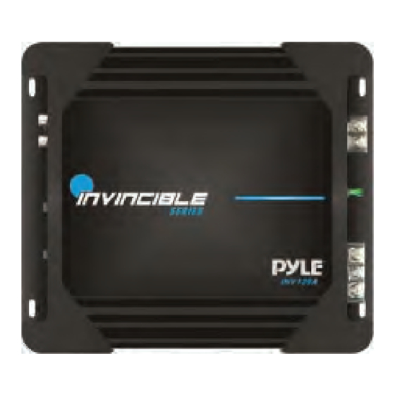
INV139A/INV239A Top View
Shows the top view of specific amplifier models, often indicating heatsink or mounting points.
INV159A/INV259A Top View
Shows the top view of specific amplifier models, often indicating heatsink or mounting points.
INV449A Top View
Shows the top view of specific amplifier models, often indicating heatsink or mounting points.
Control Functions
RCA Input Jacks
For connecting source units with RCA or Line level outputs, requiring a minimum 200mV signal.
GAIN Control
Matches amplifier sensitivity to source signal voltage; caution against long-term high volume.
SUBSONIC
Frequency adjustment for IN139MINV159A between 0Hz and 80Hz.
X-OVER
Full pass, Low Pass (LPF), and High Pass (HPF) filter settings and frequency ranges.
Bass BOOST
Boost adjustment for INV239A/INV259A (0-12dB) and other models (0, 6, 12dB).
LED
Indicates amplifier status (BLUE for normal, RED for protection mode).
Auxiliary Outputs
Allows system expansion by routing line out to a second amplifier's line input.
GND
Connect to vehicle chassis for grounding; use shortest wire of same or larger gauge.
Remote Turn On
Activates amplifier when +12V is applied, usually from the head unit's remote lead.
+12 Volt Power
Connect to the positive battery terminal via a fuse or circuit breaker.
FUSE
Protects amplifier against internal electrical damage; use identical replacements.
SPEAKERS
Terminals for connecting subwoofers or speakers.
Speaker Connection
MONO Channel System Design #1 INV139/INV159A
Illustrates connecting a mono channel system for INV139/INV159A with a subwoofer.
2 Channel System Design #1 INV239A/INV259A
Shows connecting two speakers to the amplifier in a stereo configuration.
2 Channel System Design #2 INV239A/259A
Illustrates a different 2-channel speaker connection setup for INV239A/259A.
2 Channel System Design #3 INV239A/259A
Details a 2-channel system with an inductor and capacitor for filtering.
4 Channel System Design #1 INV449A
Illustrates a 4-channel speaker connection setup for the INV449A amplifier.
4 Channel System Design #2 INV449A
Shows an alternative 4-channel speaker connection configuration for the INV449A.
Troubleshooting Guide
NO SOUND
Addresses issues with no audio output, checking fuses, power, and connections.
UNIT WILL NOT TURN ON
Troubleshooting steps for when the amplifier fails to power on, checking fuses and wires.
NO SOUND IN ONE CHANNEL
Diagnosing issues with a single channel not producing sound, checking leads and inputs.
AMP TURNING OFF MEDIUM HIGH VOLUME
Investigates amplifier shutting down at high volumes, checking speaker impedance.
Warnings
Important safety and operational warnings regarding installation and usage.


Need help?
Do you have a question about the INV139A and is the answer not in the manual?
Questions and answers