
Related Manuals for KOLARC MX500


Summary of Contents for KOLARC MX500
- Page 1 Operational Manual-OM 2023−02 Processes Multiprocess Welding MX600 MX500 MX400 OWNER'S MANUAL Visit our website at...
-
Page 2: Table Of Contents
Control Panel......................................25 Control Panel......................................26 Job List / Function Graphic / Function List..............................27 Connections, switches and mechanical components........................28 Side view........................................28 MX600 /MX500/ MX400 powersupply front / rear view..........................29 Minimum equipment for welding operations...........................30 General.........................................30 Gas-cooled MIG/MAG welding................................30 Water-cooled Mıg/mag welding................................30 Manual metal arc welding..................................30... - Page 3 Before Installation And Initial Operatin...........................31 Safety........................................31 Intended use ......................................31 Setup regulations....................................31 Assembling system components (overview)...............................32 Place the wirefeeder on the power source..............................33 Connecting the interconnecting hosepack..............................33 Correct routing of the interconnecting hosepack............................33 Establishing a ground earth connection..............................33 Connect the gas cylinder..................................34 Brake Cylinder..................................35 Brake cylinder components..................................35 Wire feeding reel....................................35...
-
Page 4: Safety Instructions
Safety Instructions Explanation of DANGER! Safety Instructions Indicates an immediate danger. ▶ Death or serious injury may result if appropriate precautions are not taken. WARNING! Indicates a possibly dangerous situation. ▶ Death or serious injury may result if appropriate precautions are not taken. CAUTION! Indicates a situation where damage or injury could occur. -
Page 5: Safety Symbols
Safety Symbols ELECTRIC SHOCK can kill. OVERUSE can cause OVERHEATING. HOT PARTS can cause severe burns. FLYING SPARKS can cause injury. FUMES AND GASES can be hazardous. STATIC (ESD) can damage PC boards. ARC RAYS can burn eyes and skin. MOVING PARTS can cause injury. -
Page 6: Environmental Conditions
The device is intended exclusively for the welding process specified on the rating plate. Utilization for any other purpose, or in any other manner, shall be deemed to be "not in accordance with the intended purpose." The manufacturer is not responsible for any damage resulting from improper use. -
Page 7: Personal Protection And Protection Of Others
This may affect a number of device types in terms of: connection restrictions criteria regarding maximum permissible grid impedance *) criteria regarding the minimum required short-circuit power *) *) both at the interface with the public grid See technical data In this case, the operator or the person using the device should check whether or not the device is allowed to be connected, where appropriate through discussion with the power supply company. -
Page 8: Danger From Flying Sparks
Take the following precautionary measures for fumes and harmful gases: Do not breathe them in. Extract them from the work area using appropriate equipment. Ensure that there is a sufficient supply of fresh air. Ensure that there is a ventilation flow rate of at least 20 m³... -
Page 9: Stray Welding Currents
Ensure suitable personal protection with dry temporary backing or cover with sufficient insulation against the ground potential. The temporary backing or cover must completely cover the entire area between the body and the ground potential. All cables and leads must be secured, undamaged, insulated, and adequately dimensioned. Replace loose connections and scorched, damaged, or inadequately dimensioned cables and leads immediately. -
Page 10: Emc Device Classifications
Position the device with sufficient insulation against electrically conductive environments, e.g., insulation against electrically conductive floors or electrically conductive mounts. Observe the following when using electrical distributors, double-headed retainers, etc.: Even the electrode of the welding torch/electrode holder not in use carries electric potential. Ensure that there is sufficient insulation when the unused welding torch/electrode holder is stored. -
Page 11: Emf Measures
EMF measures Electromagnetic fields may cause health problems that are not yet known: Effects on the health of persons close by, e.g., those with pacemakers and hearing aids Persons with pacemakers must seek advice from their doctor before staying in the immediate vicinity of the device and the welding process Keep distances between welding cables and the head/torso of the welder as large as possible for safety reasons... -
Page 12: Requirement For The Shielding Gas
In the event of crane attachment of the wirefeeder during welding, always use a suitable, insulating wirefeeder hoisting attachment (MIG/MAG and TIG devices). If the device is equipped with a carrier belt or handle, then this is used exclusively for transport by hand. -
Page 13: Danger Posed By Shielding Gas Leak
Danger Posed by Risk of asphyxiation due to uncontrolled shielding gas leak Shielding Gas Leak Shielding gas is colorless and odorless and may suppress the oxygen in the ambient air in the event of leakage. Ensure there is a sufficient supply of fresh air with a ventilation flow rate of at least 20 m³... -
Page 14: Maintenance And Repair
Always secure the shielding gas cylinder well and remove before transporting by crane. Only the original coolant from the manufacturer is suitable for use in our devices due to its properties (electrical conductivity, anti-freeze, material compatibility, flammability, etc.) Only use appropriate original coolant from the manufacturer. Do not mix original coolant from the manufacturer with other coolants. -
Page 15: Disposal
Copyright of these Operating Instructions remains with the manufacturer. Text and illustrations were accurate at the time of printing. Kolarc reserves the right to make changes. The contents of the Operating Instructions shall not provide the basis for any claims whatsoever on the part of the purchaser. -
Page 16: Declaration Of Conformity
DECLARATION OF CONFORMITY for European Community (CE marked) products. We KOLARC MAKİNE İMALAT SAN. VE TİC. A. Ş: 2014. Cd. No: 8/1, 06930 Alcı Osb/Sincan/Ankara, declares that the product(s) identified in this declaration conform to the essential requirements and provisions of the stated Standard(s). -
Page 17: Introduction
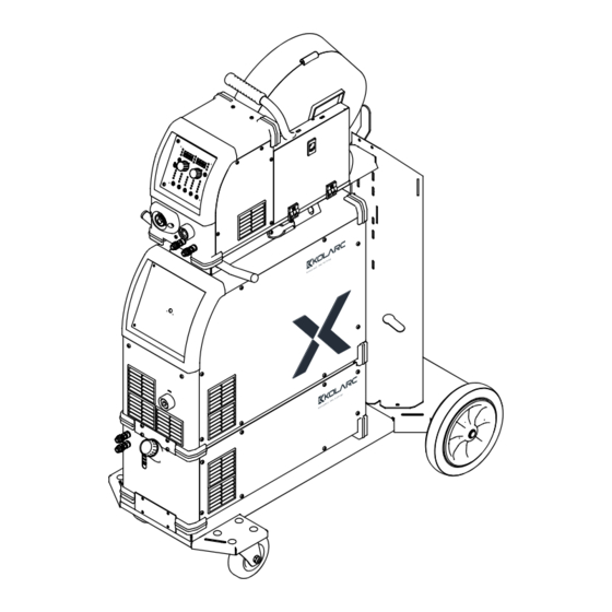
Introduction Overview (1) Wirefeeder (MX4) (2) Power source (MX600/MX500/MX400) (3) Cooling unit (WX) A modular design and ability to easily extend the system guarantee a high degree of flexibility. The device is designed for the following welding processes: - MIG/MAG Manual... - Page 18 Welding is dangerous. The following basic requirements must be met: - Adequate welding qualifications - Appropriate protective equipment - Exclusion of unauthorized persons Do not use the functions described here until you have fully read and understood the following documents: - These Operating Instructions - All system component Operating Instructions, especially the safety rules...
-
Page 19: Duty Cycle
Duty Cycle Duty Cycle is percentage of 10 minutes that unit can weld at rated load without overheating. If unit overheats, output stops, a Help message is displayed and cooling fan runs. Wait fifteen minutes for unit to cool. Reduce amperage or voltage, or duty cycle before welding. 60% Duty Cycle 6 Minutes Welding 4 Minutes Resting... -
Page 20: Connection Input Power
If no mains cable is connected, a mains cable that is suitable for the connection voltage must be fitted before commissioning. A strain-relief device for the following cable cross-sections is fitted to the power source: Power source Cable cross-section MX600 Pulse AWG 12 *) MX500 Pulse AWG 10 *) MX400 Pulse AWG 10 *) Strain-relief devices for other cable cross-sections must be designed accordingly. -
Page 21: Receptacle Information
Receptacle Information Cablo Molex Name Letter Socet Voltage Read 3 - 4 24 VAC 24 VAC Generator-Powered Operation Generator The power source is generator-compatible. powered operation The maximum apparent power S1max of the power source must be known in order to select the correct generator output. -
Page 22: Commissioning
Commissioning Safety WARNING! An electric shock can be fatal. If the power source is connected to the grid during installation, there is a danger of serious personal injury and property damage. ▶ Only carry out work on the device when the power source’s power switch is in the - O - position. -
Page 23: Brief Description Of Mig/Mag Pulsed Synergic Welding
Brief description MIG/MAG pulsed synergic of MIG/MAG pulsed synergic MIG/MAG pulsed synergic welding is a pulsed arc process with a controlled material transfer. welding In the base current phase, the energy input is reduced to such an extent that the arc barely burns steadily and the surface of the workpiece is preheated. -
Page 24: Vrd: Safety Principle
Applies to MMA welding mode: Within 0.3 seconds of the end of welding: - VRD is active again - Restriction of the output voltage to 35 V is ensured again NOTE! MX600/MX500/MX400 power sources comes with the standard VRD safety parameters. -
Page 25: Control Panel
Control panel (11) (10) (12) Designed by Checked by Approved by Date Date Designed by Checked by Approved by Date Date Gizem 14.10.2021 Gizem 14.10.202 Edition Sheet 1 / 1 (13) (17) (14) (15) (16) (1) Selection Knob (left) For changing the sheet thickness, welding current, and wire speed parameters rotate the black knob (2) Wire Feed Speed It is used to control the wire feed speed (meter/minute) (3) Welding Current... -
Page 26: Control Panel
(6) Selection Knob (right) For changing the arc length correction, welding voltage, and arc-force dynamic parameters (7) Program Memory This shows the working welding program memory. (8) Voltage This helps you to see the voltage or adjust it once required (9) Pulse / arc-force dynamic correction For continuously correcting the droplet detachment force in MIG/MAG pulsed synergic welding... -
Page 27: Job List / Function Graphic / Function List
Job List Function Graphic Function List... -
Page 28: Connections, Switches And Mechanical Components
FNC key is pressed and hold for three seconds helps you to select the functions as given on the Function Table (given on page number 27) SPCL SPCL key if pressed and hold for three seconds helps you to select between 2T/4T and S2T/S4T functions. -
Page 29: Mx600 /Mx500/ Mx400 Powersupply Front / Rear View
MX600 / MX500 / MX400 power supply front/rear view Designed by Checked by Approved by Date Date Designed by Checked by Approved by Date Date Gizem 14.10.2021 Gizem 14.10.202 Edition 1 / 1 Sheet (1) On/Off Switch: To enable and disable the power supply. -
Page 30: Minimum Equipment For Welding Operations
Water-cooled interconnecting hosepack Wire electrode Manual metal arc Power source welding Grounding cable Electrode holder Rod electrodes Minimum MX600 / MX500 / MX400 Syn power source equipment Grounding cable 120 mm² for arc air Welding torch gouging Compressed air supply... -
Page 31: Before Installation And Initial Operatin
Before Installation And Initial Operation Safety WARNING! Operating the device incorrectly can cause serious injury and damage to property. ▶ Do not use the functions described here until you have fully read and understood the Operating Instructions. WARNING! An electric shock can be fatal. If the power source is connected to the grid during installation, there is a danger of serious personal injury and property damage. -
Page 32: Assembling System Components (Overview)
Assembling WARNING! system components (overview) Work performed incorrectly can cause serious injury and damage. ▶ The following activities must only be carried out by trained and qualified personnel. ▶ Please note the information in the “Safety instructions” chapter! The following diagram is intended to provide you with an overview of how the individual system components are put together. -
Page 33: Place The Wirefeeder On The Power Source
Place the CAUTION! wirefeeder on the power source Danger of personal injury and damage to equipment due to falling wirefeeder. ▶ Ensure that the wirefeeder is firmly seated on the pivot pin and that the devices, upright brackets, and trolley are positioned securely. Connecting the WARNING! interconnecting... -
Page 34: Connect The Gas Cylinder
Connecting the WARNING! cylinder Danger of severe injury and damage to property if gas cylinders fall over. When using gas cylinders: ▶ Place them on a solid, level surface in such a way that they remain stable ▶ Secure the gas cylinders to prevent them from falling over ▶... -
Page 35: Brake Cylinder
Brake Cylinder Brake Cylinder Components ▶ Place the safety ring on the brake cylinder according to the image on the right. ▶ Be sure to correctly assemble the brake cylinder components according to the image below. Wire Feeding Reel ▶ Assemble the Wire Feed Roller and Brake Cylinder in accordance with the image. -
Page 36: Feed Rollers Placement / Changing
Feed rollers CAUTION! placement / changing Danger due to sudden raising of the feed rollers. Serious injuries may occur. ▶ Keep your fingers away from the left and right areas of the arm when unlocking the handle. 1. In this photograph we can see the wire feeder unit in its proper form 2. -
Page 37: Mig/Mag Welding
MIG/MAG Welding Safety WARNING! Operating the device incorrectly can cause serious injury and damage to property. ▶ Do not use the functions described here until you have fully read and understood the Operating Instructions. ▶ Do not use the functions described here until you have fully read and understood all of the Operating Instructions of the system components, especially the safety rules. -
Page 38: Mig/Mag Synergic Welding
MIG/MAG Synergic Welding MIG/MAG 1. Press the “Material” button (as denoted by 13 on page number 25) to select the filler metal to be synergic used. welding 2. Press the “Wire diameter” button (as denoted by 14 on page number 25) to select the diameter of the wire electrode used. -
Page 39: Xdeep / Xroot / Xcold
Perfect root welding for pipes The Kolarc XRoot welding process has been developed for short arc welding with reduced heat input, root pass welding of steel, stainless steel and high alloy steel. It provides excellent gap bridging with high arc stability for root welding in all positions. -
Page 40: Xstabil / Position / Duo Pulse
Safe application in difficult welding positions Easy control in difficult welding positions With the Kolarc Position welding solution, faster and easier control is achieved in difficult welding positions such as flat, horizontal, vertical and ceiling welding. It also provides better control in high... -
Page 41: Corrections During Welding
Corrections during The arc length correction and arc-force dynamic parameters can be used to optimize the welding welding result. Arc length correction: - = shorter arc, reduced welding voltage 0 = neutral arc + = longer arc, increased welding voltage Pulse / arc-force dynamic correction For continuous correction of the droplet detachment force in MIG/MAG pulsed synergic welding... -
Page 42: Manual Metal Arc Welding
Corrections during To obtain the best possible welding results, the arc-force dynamic parameter will sometimes welding need to be adjusted. 1 Press the “Parameter selection” button to select the arc-force dynamic parameter 2 Use the selection dial to set the desired arc-force dynamic value The welding parameter value is shown in the digital display located above it. -
Page 43: Manual Metal Arc (Mma) Welding
Manual metal arc CAUTION! (MMA) welding Danger of injury and damage from electric shock. When the power switch is switched to position ON, the rod electrode in the electrode holder is live. ▶ Ensure that the rod electrode is not touching any people or electrically conductive or grounded parts (housing, etc.) Set the Job 6 for the MMA process and the front panel screens will show the electrode welding Once the “Process”... -
Page 44: Hotstart Function (F25)
HotStart To obtain the best possible welding result, the HotStart function will sometimes need to function (F25) be adjusted. Advantages Improved ignition properties, even when using electrodes with poor ignition properties Better fusion of the parent material during the start-up phase, meaning fewer coldshut defects Slag inclusions largely avoided Function... -
Page 45: Arc Air Gauging
Arc Air Gauging Safety WARNING! Operating the device incorrectly can cause serious injury and damage to property. ▶ Do not use the functions described here until you have fully read and understood the Operating Instructions. ▶ Do not use the functions described here until you have fully read and understood all of the Operating Instructions of the system components, especially the safety rules. -
Page 46: Electrical Diagram
Electrical Diagram Black 1-Black 2 Black 1-Black 2 Communication Black 3-Black 4 Black 3-Black 4 Fuse Black 5 Black 6 Black 6 Black 7 Black 7 Black 8 POWER UNIT- VARYO CABLE Black 8 Black 5 Black 9 Black 9 Black GND 7-Pin FEMALE 7-Pin MALE... -
Page 47: Electrical Diagram
Yellow-Green JACK(+) Electrode Black Black Main Transformer Al. Heatsink Output Diode1/2 White Blue Blue White Output Diode 2/2 Grey Grey White Black JACK(-) Varyo Kolarc Wiring Diagram Company: Kolarc Makina Machine: MX-500 Revision: V0.1 Male Connector Drawn By: Talha ÇETİNCEVİZ... - Page 48 CAUTION! Risk of personal injury due to loud operating noise. ▶ Use suitable hearing protection during arc air gouging! 1 Set the power switch to position - I -: all indicators on the control panel briefly illuminate 2 Press the “Process” button to select the MMA welding process: The welding voltage is applied to the welding socket with a three second time lag.
-
Page 49: Querying The Source Circuit Inductance
Querying The Source Circuit Inductance General Significant effects of the placement of the hose packages on the welding circuit inductance information has an impact on the welding process. The best possible welding result It is important to position the hosepack correctly in order to obtain Welding circuit Welding circuit inductance finally calculated by means of setting parameter “L”... -
Page 50: Troubleshooting
Troubleshooting General The devices are equipped with an intelligent safety system, which largely negates the need for melting-type fuses. Melting-type fuses therefore no longer need to be replaced. After a possible malfunction has been remedied, the device is ready for use again. Safety WARNING! Work that is performed incorrectly can cause serious injury and damage to property. -
Page 51: Error Resolution Table
Error Resolution Table Error-1 It is a phase error. Occurs when any of the phases does not reach the machine. Error-3 It is an IGBT thermal fault. It occurs when IGBTs overheat. (It is used in the SAW model.) Error-4 Transformer thermal fault. - Page 52 Kolarc Makine İmalat Sanayi ve Ticaret AŞ www.kolarc.com...
Need help?
Do you have a question about the MX500 and is the answer not in the manual?
Questions and answers