Advertisement
Table of Contents
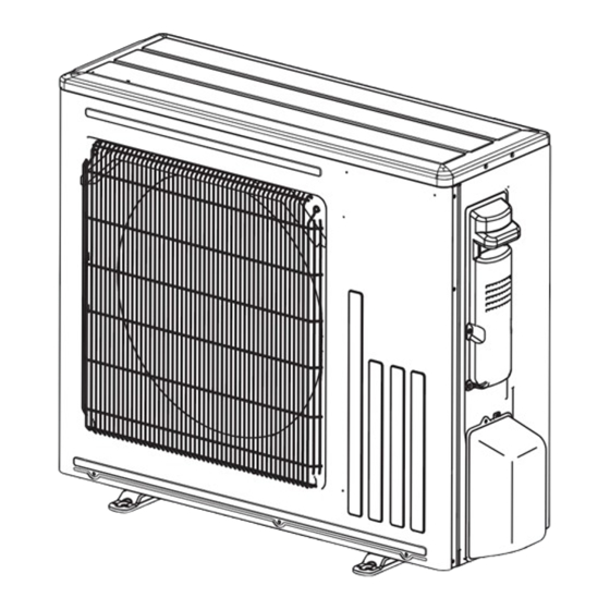
OUTDOOR UNIT
SERVICE MANUAL
Models
SUZ-SWM30VA.TH
SUZ-SHWM30VAH.TH
SUZ-SWM40VA2.TH
SUZ-SWM40VA2-SC.TH
SUZ-SHWM40VAH.TH
SUZ-SHWM40VAH-SC.TH
SUZ-SWM60VA2.TH
SUZ-SWM60VA2-SC.TH
SUZ-SHWM60VAH.TH
SUZ-SHWM60VAH-SC.TH
SUZ-SWM30VA
SUZ-SHWM30VAH
SUZ-SWM40VA2
SUZ-SWM40VA2-SC
SUZ-SHWM40VAH
SUZ-SHWM40VAH-SC
SUZ-SWM60VA2
SUZ-SWM60VA2-SC
HFC
utilized
R32
SUZ-SWM80VA2.TH
SUZ-SWM80VAH2.TH
SUZ-SWM100VA.TH
SUZ-SWM100VAH.TH
Revision:
• Specification has been
OCH796 is void.
Indoor unit service manual
EHST30D/ERST30D Series (OCH714)
CONTENTS
1. SAFETY PRECAUTION ······················· 3
2. PART NAMES AND FUNCTIONS ·········· 5
3. SPECIFICATION ································ 6
4. NOISE CRITERIA CURVES ················ 10
5. OUTLINES AND DIMENSIONS ··········· 12
6. WIRING DIAGRAM ··························· 14
8. ACTUATOR CONTROL ····················· 20
9. SERVICE FUNCTIONS ······················ 21
10. TROUBLESHOOTING ······················· 25
11. DISASSEMBLY INSTRUCTIONS ········· 40
PARTS CATALOG (OCB796)
November 2022
No. OCH796
REVISED EDITION-A
updated in REVISED
EDITION-A.
Advertisement
Table of Contents

Related Manuals for Mitsubishi Electric ERST30D Series


Summarization of Contents
SAFETY PRECAUTION
Servicing Precautions and Component Repair
Covers general servicing, component repair, intrinsic safety, and cabling safety.
Refrigerant Handling and System Safety
Details refrigerant handling, detection, removal, charging, decommissioning, labeling, and recovery safety.
PART NAMES AND FUNCTIONS
Outdoor Unit Component Identification
Identifies key external components like air inlets, outlets, and piping connections.
SPECIFICATION
Initial Model Specifications
Covers power, compressor, fan, noise, dimensions, weight, and piping for initial SUZ models.
Expanded Model Specifications
Details operating ranges, water temperatures, and piping sizes for larger SUZ models.
Electric Component Specifications
Lists specifications for main electrical components like capacitors, fuses, and modules.
NOISE CRITERIA CURVES
Noise Levels for SUZ-S(H)WM30VA(H) Models
Presents octave band sound pressure levels for cooling and heating for SUZ-S(H)WM30VA(H).
Noise Levels for SUZ-SWM40VA2(-SC) Models
Presents octave band sound pressure levels for cooling and heating for SUZ-SWM40VA2(-SC).
OUTLINES AND DIMENSIONS
Dimensions for SUZ-SWM30VA Series
Provides external dimensions, required space, and connection details for smaller models.
Dimensions for SUZ-SHWM60VAH Series
Presents external dimensions and required space for larger SUZ model series.
WIRING DIAGRAM
Wiring for SUZ-SWM30VA Series
Illustrates electrical connections for SUZ-SWM30VA, SUZ-SWM40VA2, and SUZ-SWM60VA2 models.
Wiring for SUZ-SHWM60VAH Series
Shows electrical connections for SUZ-SHWM60VAH, SUZ-SWM80VA2, and SUZ-SWM100VA models.
REFRIGERANT SYSTEM DIAGRAM
Refrigerant Circuit for SUZ-SWM30VA Series
Depicts refrigerant flow and components for SUZ-SWM30VA and SUZ-SWM40VA2/60VA2 models.
Refrigerant Circuit for SUZ-SHWM60VAH Series
Illustrates the refrigerant circuit for SUZ-SHWM60VAH, SUZ-SWM80VA2/VAH2 models.
ACTUATOR CONTROL
Fan Motor and Reversing Valve Control
Explains control logic for the outdoor fan motor and reversing valve coil.
Sensor-Actuator Relationships
Maps sensors to their purpose and controlled actuators like compressor, LEV, and fan.
SERVICE FUNCTIONS
Field Configuration Settings
Adjustments for defrost temperature and breaker size.
Operation Monitoring Introduction
Introduces request codes for monitoring outdoor unit status and parameters.
TROUBLESHOOTING
Cautions and Procedures
Provides general safety guidelines and step-by-step troubleshooting procedures.
Symptom-Based Troubleshooting Table
Correlates LED indications, symptoms, conditions, and remedies.
Component Diagnostic Flows
Diagnostic flowcharts for checking key components like compressors, motors, and PCBs.
Test Points and Voltage Specifications
Diagrams showing test points on the inverter P.C. board and associated voltage values.
DISASSEMBLY INSTRUCTIONS
Removing Outer Panels and Cabinet
Steps to access internal components by removing outer panels and cabinet for SUZ-SWM30VA series.
Inverter and P.C. Board Removal
Detailed instructions for removing the inverter assembly and its associated P.C. board.
Internal Component Removal
Procedures for detaching R.V. coil, thermistors, fan motor, and other internal parts.
Compressor and Valve Removal
Steps for removing the compressor, 4-way valve, and associated piping.
Need help?
Do you have a question about the ERST30D Series and is the answer not in the manual?
Questions and answers