
Related Manuals for vacuubrand MD 12C


Summary of Contents for vacuubrand MD 12C
- Page 1 1 of 56 Technology for Vacuum Systems Instructions for use ME 16C - MZ 8C - MD 8C - MD 12C - MV 10C Chemistry diaphragm pumps...
- Page 2 VACUU•LAN (US-Reg.No 3,704,401), VACUU•BUS , VACUU•CONTROL ® ® ® Peltronic , VARIO (US-Reg.No 3,833,788), VACUUBRAND (US-Reg.No ® ® ® 3,733,388) and also the shown company logos are registered trademarks of VACUUBRAND GMBH + CO KG in Germany and/or other countries.
- Page 3 page 3 of 56 Achtung: Die vorliegende Betriebsanleitung ist nicht in allen EU-Sprachen verfügbar. Der Anwender darf die beschriebenen Geräte nur dann in Betrieb nehmen, wenn er die vorliegende Anleitung versteht oder eine fachlich korrekte Übersetzung der voll- ständigen Anleitung vorliegen hat. Die Betriebsanleitung muss vor Inbetriebnahme der Geräte vollständig gelesen und verstanden werden, und alle geforderten Maß- nahmen müssen eingehalten werden.
- Page 4 page 4 of 56 Bemærk: Denne manual foreligger ikke på alle EU sprog. Brugeren må ikke be- tjene apparatet hvis manualen ikke er forstået. I det tilfælde skal en teknisk korrekt oversættelse af hele manual stilles til rådighed. Manual skal være gennemlæst og forstået før apparatet betjenes og alle nødvendige forholdsregler skal tages.
- Page 5 page 5 of 56 Figyelem! Ez a kezelési utasítás nem áll rendelkezésre az EU összes nyelvén. Ha a felhasználó nem érti jelen használati utasítás szövegét, nem üzemeltetheti a készüléket. Ez esetben a teljes gépkönyv fordításáról gondoskodni kell. Üzembe helyezés előtt a kezelőnek végig kell olvasnia, meg kell értenie azt, továbbá az üzemeltetéshez szükséges összes mérést el kell végeznie.
- Page 6 page 6 of 56 Attentie: Deze gebruiksaanwijzing is niet in alle talen van de EU verkrijgbaar. De gebruiker moet niet met dit apparaat gaan werken als voor hem/haar de gebruiks- aanwijzing niet voldoende duidelijk is. Bij gebruik van deze apparatuur is het nood- zakelijk een technisch correcte vertaling van de complete gebruiksaanwijzing te hebben.
- Page 7 page 7 of 56 Varning: Denna instruktion är inte tillgänglig på alla språk inom EU. Användaren får inte starta utrustningen om hon/han inte förstår denna instruktion. Om så är fallet måste en tekniskt korrekt instruktion göras tillgänglig. Instruktionen måste läsas och förstås helt före utrustningen tas i drift och nödvändiga åtgärder göres.
-
Page 8: Table Of Contents
page 8 of 56 Contents Safety information! ............. 9 Important information! ................. 9 General information ................11 Intended use..................11 Setting up and installing the equipment ..........12 Ambient conditions ................14 Operating conditions ................. 15 Safety during operation ..............17 Maintenance and repair..............19 Important information: Equipment marking (ATEX) ..... -
Page 9: Safety Information
Make operating personnel aware of dangers arising from the pump and the pumped substances. VACUUBRAND disclaims any liability for inappropri- ate use of these pumps and for damage from failure to follow instructions contained in this manual. - Page 10 page 10 of 56 ➨ DANGER indicates a hazardous situation which, if not avoided, will result in death or serious injury. + WARNING indicates a hazardous situation which, if not avoided, could result in death or serious injury. • CAUTION indicates a hazardous situation which, if not avoided, could result in minor or moderate injury.
-
Page 11: General Information
page 11 of 56 General information Remove all packing material from the packing box. Re- NOTICE move the product from its packing-box and retain all pack- aging until the equipment is inspected and tested. Re- move the protective caps from the inlet and outlet ports and retain for future use. -
Page 12: Setting Up And Installing The Equipment
page 12 of 56 + Do not use the pump to generate pressure. + The pumps are designed for ambient temperatures during operation between +50°F and +104°F (+10°C and +40°C). Periodically check maximum tempera- tures if installing the pump in a cabinet or a housing. Make sure ventilation is adequate to maintain recom- mended operating temperature. - Page 13 page 13 of 56 + Due to the high compression ratio, the pump may gen- erate overpressure at the outlet. Check pressure com- patibility with system components (e.g., exhaust pipe- line or exhaust valve) at the outlet. + Do not permit any uncontrolled pressurizing. Make sure that the exhaust pipeline cannot become blocked.
-
Page 14: Ambient Conditions
page 14 of 56 • Direction of rotation of pumps with three phase motor: Pumps wired ready for connection with three phase motor are supplied with a mains plug. The elec- trical wiring is laid out for a right-handed rotary field. Checking the direction of rotation: The three phase socket has to be checked, and if nec- essary corrected, by an electrician. -
Page 15: Operating Conditions
page 15 of 56 + Do not use this product in an area where it can fall or be pulled into water or other liquids. + P ay attention to the permissible maximum ambient and gas inlet temperatures (see „Technical data“, pg. 23). - Page 16 page 16 of 56 ➨ The pumps are not suitable to pump any of the sub- stances listed below. Do not pump: - unstable substances - substances which react explosively under impact (mechanical stress) without air - substances which react explosively when being ex- posed to elevated temperatures without air, - substances subject to auto-ignition, - substances which are inflammable without air...
-
Page 17: Safety During Operation
page 17 of 56 Safety during operation ➨ Adopt suitable measures to prevent the release of dan- gerous, toxic, explosive, corrosive, noxious or pollut- ing fluids, vapors and gases. To prevent any emission of such substances from the pump outlet, install an appropriate collecting and disposal system and take protective action for pump and environment. - Page 18 page 18 of 56 + Interruption of the pump (e.g., due to power failure), failure of connected components or of parts of the sup- ply, or change in parameters must not be allowed to lead to dangerous conditions. In case of a diaphragm failure or in case of a leak in the manifold, pumped substances might be released into the environment or into the pump housing or motor.
-
Page 19: Maintenance And Repair
For details and for the online ”Instructions for repair” man- ual see www.vacuubrand.com. In normal use, the lifetime of the diaphragms and valves is typically 15,000 operating hours. Bearings have a typi- cal durability of 40000 h. - Page 20 page 20 of 56 ➨ Ensure that the pump cannot be operated acciden- tally. Never operate the pump if covers or other parts of the pump are disassembled. ➨ Switch off the pump. Disconnect the electrical power cord and wait five seconds before starting maintenance to allow the capacitors to discharge.
-
Page 21: Important Information: Equipment Marking (Atex)
The overall category of the equipment depends on the connected com- ponents. If the connected components do not comply with the classifi- cation of the VACUUBRAND equipment, the specified category of the VACUUBRAND equipment is no longer valid. Vacuum pumps and vacuum gauges in category 3 are intended for con- nection to equipment in which during normal operation explosive atmo- spheres caused by gases, vapors or mists normally don’t occur;... - Page 22 page 22 of 56 • The equipment is designated for an ambient and gas inlet temperature during operation of +10 to +40°C. Never exceed these ambient and gas inlet temperatures. If pumping / measuring gases which are not potentially explosive, extended gas inlet temperatures are permissible. See instructions for use, section “Gas inlet temperatures”...
-
Page 23: Technical Data
page 23 of 56 Technical data General technical data valid for all pumps Maximum permissible inlet pressure (absolute) (bar) (1.1) Maximum permissible outlet pressure (absolute) (bar) (1.1) Maximum pressure difference between inlet and outlet (bar) (1.1) Maximum permissible pressure 17.5 (absolute) at gas ballast valve (bar) (1.2) - Page 24 24 of 56 Type ME 16C MZ 8C MD 8C Maximum pumping speed 5.9 / 6.8 3.6 / 4.2 3.4 / 3.9 50/60 Hz (ISO 21360) (10.1 / 11.6) (6.2 / 7.1) (5.8/ 6.7) Ultimate vacuum (absolute) Torr < 60...
-
Page 25: Gas Inlet Temperatures
Outlet ETFE Inlet Stainless steel Diaphragm clamping disc ETFE carbon fiber reinforced Diaphragm PTFE Valves FFKM Valves (ME 16C) PTFE Head cover ETFE carbon fiber reinforced Housing cover insert PTFE carbon reinforced O-ring (only MV 10C) Fittings ETFE Tubing PTFE... -
Page 26: Pump Parts
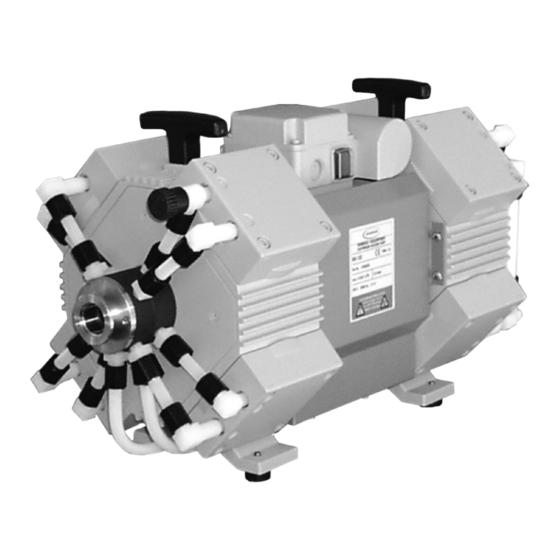
ON/OFF switch Power connection Handle Pump rating plate Distributor at the inlet Distributor at the outlet Gas ballast valve ME 16C, MZ 8C, MD 8C, MD 12C, MV 10C (fig.: MD 12C, 230V version) ME 16C, MZ 8C, MD 8C... - Page 27 27 of 56 Fittings at inlet side: ME 16C MD 12C MZ 8C MV 10C MD 8C Fittings at outlet side: ME 16C MD 12C MV 10C MZ 8C MD 8C...
-
Page 28: Use And Operation
page 28 of 56 Use and operation Installing a pump in a vacuum system ➨ If dangerous or polluting fluids could be released at the outlet, install an appropriate system to catch and dispose of those fluids. + Connect a gas-tight exhaust line at the pump outlet if necessary. -
Page 29: During Operation
page 29 of 56 • Check the power source and the pump’s rating plate to be sure that the power source and the equipment match in voltage, phase, and frequency. Keep a minimum distance of 2 in (5 cm) between the cool- NOTICE ing fan (underside the pump) and surrounding items (e.g., housing, walls, etc.), or else install an external automatic... - Page 30 page 30 of 56 pump in a cabinet or a housing. Make sure ventilation is adequate, especially if the ambient temperature is elevated. • If the pump is installed at an altitude of more than 6500 ft (2000 m) above mean sea level, check compatibility with applicable safety requirements, and adopt suit- able measures.
-
Page 31: Important Notes Regarding The Use Of Gas Ballast
Turn gas ballast cap to open valve. For condensable vapors (water vapor, sol- vents, etc.): - ME 16C / MZ 8C / MD 8C: The gas ballast valve is open if the arrow on the gas ballast cap is pointing towards the side of the pump with the rating plate. -
Page 32: Shutdown & Storage
page 32 of 56 - With gas ballast valve open, the ultimate vacuum will be reduced. - Use inert gas for gas ballast to avoid the formation of explosive mixtures. Attention: maximum supply pres- sure of inert gas: 17.5 psi (1.2 bar) absolute. - Close the gas ballast valve by turning the cap 180°. -
Page 33: Accessories
page 33 of 56 Accessories Base plate with exhaust waste vapor condenser and collecting flask ....20699949 Set of casters ..........20699981 (for base plate) Separator (inlet) ........20699980 (small flange KF DN 25) Centring ring ..........20660196 (with FPM seal) Clamping ring DN 20/25 ......20660001 (aluminium) PTFE vacuum hose (antistatic) with stainless steel small flanges. - Page 34 ® automatic control module VCL-B 11 ............20677209 On this page we offer only a small selection of VACUU•LAN options. Please contact VACUUBRAND for further ® information. Listed modules are designed for surface-mounted installation. Different catalog numbers are used for modules designed for flush-mounting with concealed tubing.
-
Page 35: Troubleshooting
page 35 of 56 Troubleshooting Fault Possible cause Remedy ❑ Pump does not ➨ Electrical power cord ✔ Plug in power cord. start or stops im- not plugged in, electri- Check fuse. mediately. cal supply failure? ➨ Overpressure in outlet ✔... - Page 36 page 36 of 56 Fault Possible cause Remedy ❑ Pump too noisy. ➨ Atmospheric or high ✔ Connect hose or silencer pressure at the pump to pump outlet. Be careful inlet? not to cause outlet over- pressure, especially with condensable vapors. ➨...
-
Page 37: Replacing Diaphragms And Valves
page 37 of 56 Replacing diaphragms and valves + Please read section ”Replacing diaphragms and valves” com- pletely before starting maintenance. The pictures may show other versions of pumps. This does not change the method of replacing diaphragms and valves. ➨... - Page 38 - Regular maintenance will improve the lifetime of the pump and also protect both users and the environment. Set of seals (diaphragms, valves, O-rings) ..........20696821 Set of seals for ME 16C (diaphragms, valves) ........8x 20696813 Diaphragm key (w/f 66) ................20636554 Tools required (metric):...
- Page 39 page 39 of 56 View of the disassembled pump head parts Pump head parts: A: Housing cover with housing I: Connecting rod cover insert J: Housing B: Valves K: Cover plate C: O-rings L: Manifold cover (only at outlet) D: Head cover M: Countersunk screw E: Diaphragm clamping disc N: Union nut...
-
Page 40: Cleaning And Inspecting The Pump Heads
+ Do not remove the elbow fittings from the pump heads; during reassembly a leak may result. Fittings and tubing of the different pump models: Inlet side ME 16C MD 12C MZ 8C MV 10C MD 8C... -
Page 41: Replacing The Diaphragm
41 of 56 Outlet side ME 16C MZ 8C MV 10C MD 12C MD 8C ➨ Disassemble the housing covers (A) to check the diaphragms and valves. ➨ Unscrew four Allen screws (R) with a 5mm wide Allen key. Remove the housing cover... - Page 42 page 42 of 56 ➨ Check for washers (H) between the diaphragm support disc (G) and the connecting rod (I) . Do not mix the washers from the different pump heads, since these are set at the factory to ensure proper pump per- formance.
-
Page 43: Assembling The Pump Heads
page 43 of 56 Assembling the pump heads ➨ Place the pump in a way that the pump head to be assembled is at the top. Support the pump appropriately. ➨ Bring the diaphragm (F) into a position in which it is in contact with the housing (J) and centered with respect to the bore. - Page 44 page 44 of 56 Individual performance check of a pump head: Check the performance by measuring the vacuum at the inlet port of the individual pump head: Use a suitable vacuum gauge (e.g., DVR 2pro, cat. no.: 20682906), be- ing sure that it is correctly calibrated. Measure the vacuum at the inlet port (marked ”IN”).
-
Page 45: Replacing The Valve At The Distributor (Outlet Side)
page 45 of 56 Replacing the valve at the distributor (outlet side) + Only MD 12C / MV 10C ➨ Loosen the union nut of the hose running directly to the manifold cover (L) of the distributor (P) with an open-ended wrench (w/f) 17. Loosen only the union nut at the pump head, not the one at the distributor. -
Page 46: Assembling The Connecting Hoses
page 46 of 56 Assembling the connecting hoses ➨ Slip the hoses (O) onto the hose connec- tors by turning the fittings (Q) with an open- ended wrench w/f 14 (w/f 16 at outlet). ➨ Tighten the union nuts (N) of the hose con- nections at the pump heads with an open- ended wrench w/f 17. -
Page 47: Repair - Maintenance - Return - Calibration
3 or 4. These devices cannot be checked, maintained or re- paired. Also decontaminated devices must not returned to VACUUBRAND due to a residual risk. The same conditions apply to on-site work. No repair, maintenance, return or calibration is possi- ble unless the correctly completed health and safety clearance form is returned. - Page 48 page 48 of 56 If you do not wish a repair on the basis of our quotation, the device may be returned to you disassembled and at your expense. In many cases, the components must be cleaned in the factory prior to repair. For cleaning we use an environmentally friendly water based process.
-
Page 49: Warranty
49 of 56 Warranty VACUUBRAND shall be liable for insuring that this prod- uct, including any agreed installation, has been free of de- fects at the time of the transfer of risk. VACUUBRAND shall not be liable for the consequences... -
Page 50: Health And Safety Clearance Form
* Contact the VACUUBRAND service absolutely before dispatching the device. ** Devices which have been in contact with biological substances of risk level 3 or 4 cannot be checked, main- tained or repaired. Also decontaminated devices must not returned to VACUUBRAND due to a residual risk. ☐... -
Page 51: Ec Declaration Of Conformity Of The Machinery
Bevollmächtigter für die Zusammenstellung der technischen Unterlagen / Person authorised to compile the technical file / Personne autorisée à constituer le dossier technique: Dr. J. Dirscherl · VACUUBRAND GMBH + CO KG · Alfred-Zippe-Str. 4 · 97877 Wertheim · Germany Wertheim, 01.07.2018 . -
Page 52: China Rohs
China RoHS DECLARATION OF CONFORMITY – China RoHS 2 VACUUBRAND GMBH + CO KG has made reasonable efforts to ensure that hazardous mate- rials and substances may not be used in its products. In order to determine the concentration of hazardous substances in all homogeneous materials of the subassemblies, a “Product Conformity Assessment”... - Page 53 (Pb), mercury (Hg), cadmium (Cd), hexavalent chromium (Cr+VI), polybrominated biphenyls (PBB), and polybrominated diphenyl ethers (PBDE). Products manufactured by VACUUBRAND may enter into further devices (e.g., rotary evaporator) or can be used together with other appliances (e.g., usage as booster pumps).
- Page 54 page 54 of 56...
- Page 55 page 55 of 56...
- Page 56 Alfred-Zippe-Str. 4 · 97877 Wertheim / Germany T +49 9342 808-0 · F +49 9342 808-5555 info@vacuubrand.com · www.vacuubrand.com VACUUBRAND GMBH + CO KG - Technology for Vacuum Systems - © 2018 VACUUBRAND GMBH + CO KG Printed in Germany Manual-no.: 20901020 / 07/01/2018...
Need help?
Do you have a question about the MD 12C and is the answer not in the manual?
Questions and answers