Table of Contents
Advertisement
Advertisement
Table of Contents

Related Manuals for Pepperl+Fuchs KFU8-VCR-1


Summarization of Contents
Introduction
Content and Scope
Outlines the information covered in the document for product lifecycle stages.
Target Audience and Personnel Qualifications
Defines responsibilities for product handling and required training.
Document Symbols and Warnings
Explains warning and informative symbols to ensure user safety.
Product Specifications
Functionality Overview
Describes signal conditioners as isolators for galvanic isolation and signal conditioning.
Housing Styles and Types
Details the three different housing widths (12.5mm, 20mm, 40mm) for K-System devices.
Removable Terminal Blocks
Explains removable terminal blocks for simplified connection and cabinet assembly.
Terminal Designation
Provides guidance on terminal designation for different housing types.
Color Identification
Explains the meaning of device colors related to power supply types.
Status Indicators (LEDs)
Details the function and meaning of different LED indicators on the isolators.
Operating Elements
Introduces various operating elements like DIP switches, rotary switches, and potentiometers.
Keypad, LC Display, and PC Configuration
Covers device configuration via keypad, display, and parameterization software.
Labeling and Mounting Rail
Discusses label carriers for devices and mounting on DIN rails.
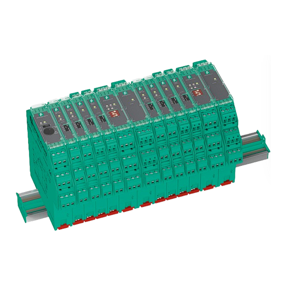
Power Rail System
Introduces Power Rail for power delivery and bus signal transfer.
Mounting and Installation
General Mounting Principles
Covers safety precautions and general mounting instructions for devices.
Mounting in Hazardous and Non-Hazardous Areas
Safety requirements for mounting in explosive atmospheres and non-hazardous areas.
Mounting Orientations
Discusses vertical and horizontal mounting without spacing.
Mounting Conditions and Separation Distances
Specifies conditions for higher temperatures and required separation distances.
Terminal Block Mounting and Connection Safety
Safety precautions for mounting terminal blocks and electrical connection.
Field and Control Side Connections
Instructions for connecting field devices and control systems, including relay outputs.
Power Supply Connection Options
Details available power supply voltages and connection methods without Power Rail.
Power Supply with Power Rail
Explains using Power Rail for 24 V DC supply, its benefits, and components.
Power Feed Module and Non-Redundant Supply
Covers power feed modules, safety, and non-redundant power distribution.
Redundant Power Supply
Explains redundant power supply configuration for high availability.
Direct Power Supply with Power Supplies
Details using specific power supplies for direct connection to the Power Rail.
Establishing Communication via Software
Instructions for establishing HART communication using adapters and multiplexers.
Configuration
Device Configuration Procedures
Guidance on setting operating elements as per datasheet instructions.
Operation
Fault Monitoring Mechanisms
Explains how isolators monitor line and device faults.
Fault Outputs and Indication
Describes fault transmission via LEDs, fault outputs, and line fault transparency.
Collective Error Message Output
Explains how collective error messages are output via the Power Rail.
Standard Signal Types
Discusses standard signals like 0/4-20mA and 0/2-10V for data processing.
Dismounting, Maintenance, and Repair
Circuit Disconnection Procedures
Steps to safely disconnect power, field, control, and HART communication circuits.
Signal Conditioner Dismounting
Step-by-step guide using a slotted screwdriver to remove the signal conditioner.
Technical Specifications
Electrical and Field Circuit Data
Details electrical and field circuit specifications, safety values, and conformity.
Ambient Conditions and Environmental Resistance
Specifies operating/storage temp, humidity, vibration, and shock resistance.
Mechanical Specifications and Labeling
Covers mounting, housing, dimensions, protection, connection, and labeling.
Model Number Description
Explains the structure and meaning of model number components.
Housing Types A2 and B1 Dimensions
Provides dimensions for Housing Types A2 and B1.
Housing Types B2 and C2 Dimensions
Provides dimensions for Housing Types B2 and C2.
Power Supply Housing Dimensions
Dimensions for the 4A power supply housing.
Need help?
Do you have a question about the KFU8-VCR-1 and is the answer not in the manual?
Questions and answers