Table of Contents

Related Manuals for Alltrax TXT48


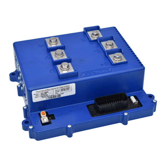
Summarization of Contents
General Safety Warnings
Usability Statement
Defines intended use for AC controllers with brushless motors and warranty limitations for other applications.
Unique Features
Low Voltage Protection
Describes the controller's function to prevent battery damage by shutting off power when voltage drops below a set limit.
Components Overview
Heavy Duty Contactors
Shows heavy-duty contactors, essential for safely switching high currents in electric vehicle systems.
Main Fuse
Displays the main fuse, a critical safety component for protecting the battery circuit from overcurrent.
Heavy Gauge Wires
Illustrates heavy gauge wires used for high current connections, ensuring proper power delivery.
Contactors (Solenoids)
Heavy Duty 400A Rating
Specifies the minimum 400A continuous and 800A inrush rating required for solenoids used with AC1 controllers.
Fuse Installation
Fuse Style and Rating
Provides guidance on selecting the correct fuse style and rating based on controller amperage.
Wiring Best Practices
Power Wiring Guidelines
Offers guidelines for routing power wiring to minimize EMC emissions and ensure practical installation in the vehicle.
Motor Phase Wiring
Provides instructions for routing motor phase wires for optimal reliability and to prevent interference with other signals.
High Current Connections
Lug Assembly Details
Describes the lug assembly and stainless steel bolts used for securing high current terminals to the controller.
Low Power Wiring
Signal Wiring Best Practices
Best practices for signal wire routing, including protection against damage and avoiding bundling with power wires.
Temp Sensor Function
Explains the function of the two-wire temp sensor and its connection path in DC conversion systems.
Speed Sensor Information
Quadrature Signal
Explains the Quadrature signal used by induction motors for speed sensing, providing up to 64 readings per minute.
Speed and Temp Sensor Cable
Encoder Pulses/Revolution Constraint
Explains the maximum encoder frequency and the method to calculate the motor speed limit based on encoder pulses.
Firmware Max Speed Constraint
States the maximum motor speed limit enforced by the controller's firmware.
Speed and Temp Sensor Wire Harness Pinouts
C3 - TE_Superseal 4P Connector
Details the C3 connector, used for the motor's speed sensor signal, noting its water-resistant design.
C2 - TE_Superseal 2P Connector
Details the C2 connector, used for the motor's temperature sensor harness, noting its water-resistant design.
C1 - JST-JWPF O8 Connector
Details the C1 connector on the controller side for the speed and temperature sensor harness, noting its water-resistant design.
Controller Dimensions
Top Down View
Displays the controller's physical dimensions as viewed from the top, including overall length and width.
Side View
Shows the controller's physical dimensions as viewed from the side, indicating height and depth.
Front View
Displays the controller's physical dimensions as viewed from the front, indicating width and height.
E-Z-GO TXT48 Conversion Overview
J1 - Main Wire Harness Connector
Identifies J1 as the main wire harness connector for the TXT48 conversion and refers to pinout details.
B+ Positive from Solenoid
Identifies the B+ terminal connection for positive power input from the solenoid in the TXT48 conversion.
E-Z-GO PDS Conversion Overview
J1 - Main Wire Harness Connector
Identifies J1 as the main wire harness connector for the PDS conversion and refers to pinout details.
B+ Positive from Solenoid
Identifies the B+ terminal connection for positive power input from the solenoid in the PDS conversion.
Programming the Controller
Download Alltrax Toolkit Software
Provides information and a link for downloading the Alltrax Toolkit software for controller programming.
Blink Codes
Throttle Type Codes
Codes indicating different types of throttles connected to the controller, represented by green LED flashes.
Brake Type Codes
Codes indicating different types of brakes connected to the controller, represented by green LED flashes.
Normal Display Status
Describes the meaning of solid green, red, and yellow lights, and blinking yellow light for controller status.
Error Code Categories
Lists categories of error codes indicated by green and red LED flashes, guiding initial troubleshooting.
Code Definitions
Circuit, Voltage, and Temperature Errors
Explains errors related to shorts, voltage levels, temperature, and pre-charge failures.
Throttle and Signal Errors
Explains errors related to throttle signal range, power faults, and brake/throttle communication.
Data and Component Errors
Explains errors concerning configuration data, relay coils, brake coils, and horn circuits.
Component Overcurrent Errors
Defines errors related to overcurrent conditions in relay coils, brake coils, and horn circuits.
Need help?
Do you have a question about the TXT48 and is the answer not in the manual?
Questions and answers