Table of Contents

Related Manuals for Alltrax PDS


Summarization of Contents
General Warnings and Safety
Safety Precautions
Essential safety measures to follow during operation and maintenance of electric vehicles.
Cautionary Notes
Important warnings regarding potential hazards and installer responsibilities for correct equipment usage.
AC1 Controller Specifications
Model and Rating
Details the AC1 controller model and its current ratings (2 Min, 5 Min, Continuous).
Operating Parameters
Covers controller voltage, temperature ranges, and input current specifications.
Supported Throttles
Lists the various throttle types compatible with the AC1 controller.
Terms and Definitions
Motor Technology Terms
Defines Internal Permanent Magnet (IPM) and Surface Mount Permanent Magnet (SMPM) motor types.
Controller Function Terms
Explains terms like KI, KP, KD, Quadrature, Sine/Cosine, ITS, KSI, and Roll Detect.
Unique Features
Low Voltage Protection
Describes the controller's feature to protect batteries from over-discharge.
Low Voltage Trigger Limits
Details the specific voltage thresholds and timeframes for low voltage shutdown.
Components Overview
Heavy Duty Contactors
Highlights the importance and visual of heavy-duty contactors used with the controller.
Main Fuse
Shows the main fuse component, essential for circuit protection.
Heavy Gauge Wires
Illustrates the heavy gauge wires required for high-current connections.
Contactors (Solenoids)
Solenoid Function and Importance
Explains the role of the solenoid as a primary disconnect and its criticality for safety.
Heavy Duty Solenoid Requirements
Details the necessary rating for solenoids used with AC1 controllers (400A continuous, 800A inrush).
Fuse Installation
Fuse Placement Guidelines
Provides acceptable locations for fuse installation within the battery circuit.
Fuse Style and Rating
Specifies the fuse style (ANN/400A) for different controller amperages.
Fuse Terminal Hardware Diagram
Illustrates the correct hardware assembly for fuse terminal connections.
Wiring Guidelines
Wiring Importance and Wire Gauge
Emphasizes wiring health and provides wire gauge recommendations for safety and performance.
Power and Motor Phase Wiring
Covers best practices for routing and managing power and motor phase wiring.
High Current Connections
Terminal Functions
Lists and describes the function of each high current terminal (B+, B-, R, U, V, W).
Lug Assembly Diagram
Provides a visual representation of the lug assembly for high current terminals.
Low Power Wiring
Signal Wiring Best Practices
Provides guidelines for routing and protecting signal wires to prevent interference.
Temp Sensor Functionality
Explains how the two-wire temp sensor functions and is routed.
Speed Sensor Information
Speed Sensor Signal Type
Describes the Quadrature signal used by induction motors and speed sensors.
Sensor Requirement for AC Conversions
States that speed sensors are currently required for all ACT induction applications.
Speed and Temp Sensor Cable
Cable Routing Recommendation
Advises against running the sensor cable parallel to high current wires.
Encoder Pulses/Revolution Constraint
Explains the maximum encoder frequency the controller accepts (10 kHz).
Firmware Max Speed Constraint
States the maximum motor speed allowed by the controller firmware (10,000 rpm).
E-Z-GO DCS Conversion
Harness Replacement Requirement
Specifies the need to replace the factory DCS harness with an E-Z-GO TXT48 harness.
Wire Harness Pinouts
C3 - Speed Sensor Connector
Describes the TE_Superseal 4P connector used for the speed sensor signal.
C2 - Temp Sensor Connector
Describes the TE_Superseal 2P connector used for the motor temp sensor harness.
C1 - Controller Side Connector
Describes the JST-JWPF O8 connector for the controller side of the sensor harness.
Alltrax Harness Pinout Details
C1 Connector Pinout
Provides detailed pin assignments for the C1 connector.
C2 Connector Pinout
Provides detailed pin assignments for the C2 connector.
C3 Connector Pinout
Provides detailed pin assignments for the C3 connector.
E-Z-GO TXT48 16-Pin Molex Pinout
Connector Diagram
Shows the female side, top-down view of the 16-pin Molex connector for TXT48.
Connector Type and Crimp Info
Specifies the connector housing (Mini-fit jr male) and wire gauge (18-24awg crimps).
TXT48 16-Pin Connector Table
PIN 1-8 Assignments
Details the functions of pins 1 through 8 of the 16-pin Molex connector.
PIN 9-16 Assignments
Details the functions of pins 9 through 16 of the 16-pin Molex connector.
E-Z-GO PDS Molex Pinout
Connector Types
Identifies the PDS Molex connectors: Flat 4 pin, Square 4 pin, Rectangle 10 pin.
Connector Usage for AC Conversions
Specifies which of the PDS connectors are used in AC conversions.
PDS Connector Pinout Table
C1 Connector Pinout
Details the pin assignments for the PDS C1 connector.
C3 Connector Pinout
Details the pin assignments for the PDS C3 connector.
C4 Connector Pinout
Details the pin assignments for the PDS C4 connector.
Controller Dimensions
Top Down View Diagram
Provides a top-down view of the controller with key dimensions indicated.
Controller Dimensions (Continued)
Side View Diagram
Presents a side view of the controller with relevant measurements.
Front View Diagram
Shows a front view of the controller with its dimensions.
E-Z-GO TXT48 Conversion Details
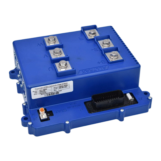
Controller and Connector Overview
Visual guide to the controller and its main connectors for TXT48 models.
Terminal Functionality
Explains the purpose of each high current terminal (B+, B-, R, U, V, W).
E-Z-GO PDS Conversion Details
Controller and Connector Overview
Visual guide to the controller and its main connectors for PDS models.
Terminal Functionality
Explains the purpose of each high current terminal (B+, B-, R, U, V, W).
Programming the Controller
Controller Configuration
Notes that controllers are pre-programmed but can be customized.
Customization and Motor Maps
Explains how to customize performance and match motor maps.
Alltrax Toolkit Software
Provides information on downloading and using the free Alltrax Toolkit software.
Blink Codes
Throttle Type Codes
Lists green LED flash patterns corresponding to different throttle types.
Brake Type Codes
Lists green LED flash patterns for different brake types.
Blink Codes Interpretation
Normal Display Status Codes
Describes the meaning of solid green, red, and yellow LED indicators.
AC Alarm Error Codes
Details error codes represented by sequences of green and red LED flashes.
Code Definitions
Short Circuit and Voltage Errors
Defines errors like Short Circuit/Output Fault, Battery Under/Over Voltage.
Temperature and Throttle Errors
Explains Over temperature, Throttle Power Fault, and Throttle Over/Under range errors.
Configuration and Signal Errors
Defines errors related to Bad Variables Loaded and Throttle/Brake Range signals.
Code Definitions (Continued)
Pre-charge and Coil Overcurrents
Defines Pre-charge Failure and overcurrents for relay and brake coils.
Horn Overcurrent
Explains the Horn Overcurrent error, indicating a short in the horn circuit.
Warranty Statement
Limited Warranty Period and Coverage
Outlines the 2-year warranty period and common exclusions for defects.
Warranty Service Authorization
Provides instructions for obtaining warranty service and returning defective products.
Disclaimer of Implied Warranties
Details disclaimers regarding implied warranties and liability limitations.
Need help?
Do you have a question about the PDS and is the answer not in the manual?
Questions and answers