Advertisement

DCX Wiring Diagram

For complete instructions and wiring diagrams for other configurations and vehicles please download our DCX Operators Manual from www.alltraxinc.com
ControllerPRO
ControllerPRO is free user friendly software for customizing your Alltrax DCX Controllers. Download your copy of ControllerPRO from www.alltraxinc.com
Configuration
Disconnect all battery charging sources while programming your DCX controller. The controllers RS-232 serial port is referenced to the B- battery connection.
Beware of any possible ground loop faults between your computer and the controller which could damage both the DCX Controller and PC, or cause personal injury.
Hardware: Use a STRAIGHT-THROUGH DB-9 pin / RS-232 serial interface cable to connect the controller to the PC. Alternatively use the preferred DB-9 pin RS-232 serial port to USB adapter.
The DCX controller must be powered before the ControllerPRO program will have any effect.
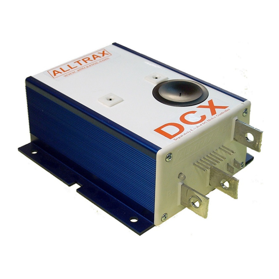
Before programming the DCX, READ THE SAFETY NOTES BELOW. For bench programming prior to installation, a fused 18V or higher battery may be used to power the controller. Connect battery negative to the B- bus bar, battery positive to pin 5+6, 9+10 (Pin 8 is blank).
If you see an error "Motor Controller is Not Responding", verify the controller is powered up and the connections are inserted correctly. If the error message continues, uninstall then reinstall the drivers for the communications cable. If the problem persists, contact Alltrax Technical Support.
Safety Notes

Alltrax also recommends a diode across the coil of the solenoid if it is not already installed. A minimum of a 100V 1A diode (a 1N4004 is suitable) is required. See complete wiring diagrams for orientation.
Working on electric vehicles, sudden unexpected events can occur, it's recommended to:
- Place the drive axle on jack stands— wheels off the floor
- When working on wiring or batteries, always remove rings and watches and use the proper safety equipment, eye protection, and insulated tools
- Never connect a computer while the vehicle is being charged
- Disconnect batteries before installing or working on the controller
LED Status Indicator
LED Blink Codes:
At power up, # of green blinks indicates configured throttle type:
1 Green = 0-5k
4 Green = EZ-GO inductive (ITS)
7 Green = CLUBCAR 5K-3-wire
Normal display status:
Solid Green: Controller ready to run
Solid Red: Controller in programming mode
Solid Yellow: Controller throttle is wide open, controller is supplying max output, and is not in current limit.
Trouble Shooting
Error code display: # of RED blinks indicates any error conditions that might exist:
- Red = Throttle Position Sensor Over Range. Check for open wires.
- Red = Under Temperature. Controller below -25C
- Red = HPD. Throttle hasn't gone to zero during this power on cycle.
- Red = Over Temperature. Controller over 95C
- Red = Open Field
- Red = Battery Under Voltage detected. Battery V < under voltage slider
- Red = Battery Over Voltage detected. Battery V > overvoltage slider
Alltrax, Inc.
1111 Cheney Creek Rd
Grants Pass, OR. 97527
Phone: 541-476-3565
Fax: 541-476-3566
- Programmable
- 300, 400, & 600 Amp
- 24 to 48 Volt DC
- Regenerative Braking
- For Shunt Wound Motor
www.alltraxinc.com

Documents / ResourcesDownload manual
Here you can download full pdf version of manual, it may contain additional safety instructions, warranty information, FCC rules, etc.
Advertisement


Need help?
Do you have a question about the DCX and is the answer not in the manual?
Questions and answers