
Subscribe to Our Youtube Channel
Related Manuals for Alltrax YDRE2 AC


Summary of Contents for Alltrax YDRE2 AC
-
Page 1: Pinout Table
Operators Manual AC Controller YDRE2 AC Alltrax Inc 1111 Cheney Creek Road, Grants Pass, OR 97527 Ph: 541-476-3565 Fax: 541-476-3566 Web Site: http://www.alltraxinc.com ©ALLTRAX INC 2023 - All Rights Reserved... - Page 2 Contact Alltrax: Phone: 541-476-3565 EXT 3 Fax: 541-476-3566 Email: Tech Support: helpdesk@alltraxinc.com Orders: orders@alltraxinc.com Shipping: shipping@alltraxinc.com General Inquires: info@alltraxinc.com Website: http://www.alltraxinc.com Facebook: http://www.facebook.com/AlltraxInc Twitter: http://www.twitter.com/Alltraxinc...
-
Page 3: Table Of Contents
WIRING HIGH CURRENT TEMP SENSOR SPEED SENSOR SPEED/TEMP CABLE HARNESS PINOUTS SPEED AND TEMP HARNESS PINOUT TABLE 23 PIN AMPSEAL YDRE2 AC PINOUT TABLE 1/2 PINOUT TABLE 2/2 CONTROLLER DIMENSIONS TOP DOWN VIEW SIDE VIEW FRONT VIEW LED BLINK CODES... -
Page 4: Warnings
• Never connect a computer while the vehicle is being charged. • Disconnect batteries before installing or working on the Alltrax controller. • Wear safety glasses. • Because hydrogen can build up due to gassing from the batteries, work in a well ventilated area. - Page 5 WILL NOT be covered by warranty. Also, any requests for design assistance or technical support outside the scope of the product intended use may be denied. Alltrax assumes no liability for any damage or injury as a result of use of the motor controllers in a non-traction or process motor application.
-
Page 6: Ac Technical Specifications
AC1 SPECIFICATIONS Model 2 Min 5 Min Continuous (Amps) (Amps) (Amps) AC1-48650 Type: 3 phase AC Operating Frequency: Controller Voltage, KSI & Reverse: 48v controllers = 16v - 60v 72v controllers = 16v - 92v Operating Temperature: -20c to 90c Environmental Operating Temperature: -20C to 50C (0F to 122F) Standby Current (Power up): KSI &... -
Page 7: Terms And Definitions
Terms and Definitions IPM: Internal Permanent Magnet SMPM: Surface Mount Permanent Magnet KI: Integral Gain for PI/PID controllers KP: Proportional Gain for PI/PID controllers KD: Derivative Gain for PI/PID controllers Quadrature: Most common type of Speed Sensor Signal used in AC Induction motor applications Sine/Cosine: Commonly used for speed sensors in IPM and SMPM motor applications. - Page 8 Unique Features Unique Features Low Voltage Protection - If battery voltage falls below your set Under Voltage limit the controller will shut off the power supply completely to prevent the batteries from getting drained to the point of damaging themselves. If you plug the controller into the toolkit software you will get a large SHUTDOWN warning to notify you of what happened.
-
Page 9: Required Component Info
COMPONENTS Heavy Duty Contactors Main Fuse Heavy Gauge Wires http://www.alltraxinc.com... -
Page 10: Solenoid/Contactors
Too small of a solenoid increases the likelihood that the contacts will weld together and not be able open. When installing a new controller, Alltrax recommends the OEM solenoids be replaced with a heavy duty version. See below for suggested sizing of solenoid replacements. -
Page 11: Main Fuse
Fuse Any application where there is a battery pack, a fuse must be installed. A fuse will open the battery circuit and prevent any serious damage from occurring. The fuse should be installed on or between the battery terminals. The main battery positive OR main battery negative OR in- between 2 batteries is an acceptable location for fuse installation. -
Page 12: Wiring
Wiring Wiring and battery health in an electric vehicle are very important and overlooked during performance upgrades. Wiring size is important for safety and proper operation of the vehicle. Undersized wires will affect the performance of controllers and can overheat. Wires should be crimped with proper sized terminals and tools to provide a clean low resistance connection. -
Page 13: High Current
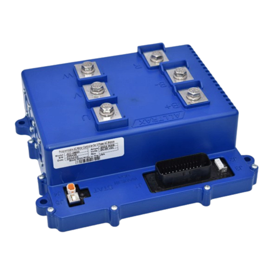
High Current Connections TERMINAL FUNCTION Battery positive to Controller Battery negative to Controller Brake Resistor Motor phase U Motor phase V Motor phase W LUG ASSEMBLY The AC controller comes with 5-6 stainless steel 1/4-20 bolts for holding the high current terminals to the controller. http://www.alltraxinc.com... -
Page 14: Temp Sensor
Low Power Wiring Signal Wiring Signal wires should be keep as short as practical. Care should be taken to protect the wires from sharp edges and rubbing. Consider the use of split loom or braided wire sheathing. Fasten bundles securely to framework. Do not route the signal wires together in the same bundle with power wires. -
Page 15: Speed Sensor
Speed Sensor Information The speed sensor is a small group of wires attached to the side of the motor. Induction motors use a Quadrature signal that gives up to 64 readings per minute. Speed sensors are currently required. Carts that came stock with an AC motor will all be equipped to use the Quadrature sensor. -
Page 16: Speed/Temp Cable
Speed and Temp sensor cable All DC conversion systems will come with a new speed and temp sensor cable to match the new AC motor. We recommend not running this harness parallel to your high current wires. An example would be zip tying them to your large gauge motor wires. Even with shielded wires this can potentialy cause issues with the signal. -
Page 17: Harness Pinouts
Wire Harness Pinouts Speed and Temp sensor harness connectors Used on all DC conversions - TE_Superseal 4P connector used for the speed sensor signal of the motor. Water resistant connector. C2 - TE_Superseal 2P connector used for the motor temp sensor harness. Water resistant connector. -
Page 18: Pinout Table
C1, C2, C3 pinouts for Alltrax harness NAME DESCRIPTION CONNECTOR Not Used Not Used Temp Sensor Lo Temp Sensor Hi CONNECTOR Temp Sensor Lo Temp Sensor Hi CONNECTOR AC OPERATORS MANUAL... -
Page 19: Pin Ampseal Ydre2 Ac
The majority of low power connections will be made through the 23 pin amp seal connector. The pinouts are different between the AC and DC G19/G22 carts running the same style connector. The factory harness should plug directly into the Alltrax controller. The image shows the carts wire harness when unplugged and looking at the face. - Page 20 23 PIN TABLE 1/2 NAME DESCRIPTION TOW/RUN switch Main positive power for the low current system. Not Used Not Used Not Used Not Used Throttle Position Low side of the Throttle position Sensor sensor Main Relay Control wire for the solenoid coil Main Relay Control wire for the solenoid coil Reverse Buzzer...
- Page 21 23 PIN TABLE 2/2 NAME DESCRIPTION Main switch Key switch power Footswitch On/Off signal from the throttle Temp Sensor Temperature Sensor Input Temp Sensor Temperature Sensor Input GRD Splice A Shift-switch Forward signal from the shifter Shift-switch Reverse signal from the shifter Charger interlock DC Receptacle for charge interlock receptacle Throttle Position...
-
Page 22: Controller Dimensions
CONTROLLER DIMENSIONS TOP DOWN VIEW AC OPERATORS MANUAL... -
Page 23: Side View
CONTROLLER DIMENSIONS SIDE VIEW FRONT VIEW http://www.alltraxinc.com... - Page 24 VEHICLE INSTALLATION DRAWINGS Don’t see a drawing that suites your needs? Visit our website for full sized, updated and more drawings. www.alltraxinc.com AC OPERATORS MANUAL...
- Page 25 YAMAHA YDRE2 AC J1- For an indepth description of the wire harness see pages 24 - 26 of this manual. B+ Positive from Solenoid J1 - Main wire harness connector B- Battery Negative J2 - Personality Switch R Large resistor connection...
- Page 26 The USB A to B cable is used to connect your motor controller to your personal computer. Using the free Allrax Toolkit you can customize your performance to match your needs. The Alltrax Toolkit software can be downloaded from: https://alltraxinc.com/alltrax-tool-kit/ No purchase necessary...
-
Page 27: Led Blink Codes
BLINK CODES On power up, the controller will blink out a throttle code and then a Status or Error Code (see below) Throttle Type Codes: 1 Green LED Flash 2-wire 0-5k throttle 2 Green LED Flash 2-wire 5K-0 throttle 3 Green LED Flash 0-5V throttle 4 Green LED Flash EZGO ITS throttle... -
Page 28: Alarm Codes
BLINK CODES Normal Display Status: Solid Green Light Controller Ready to Run Solid Red Light Controller in programming mode Solid Yellow Light Throttle is wide open and the controller is NOT in Current Limit Blinking Yellow Light Throttle is wide open, but the controller is in Current Limit Error Codes: AC alarm codes flash a sequence of green then red. All alarms are self clearing... -
Page 29: Code Definitions
Check and/or replace throttle. Change throttle type to correct throttle installed on car. • Bad Variable Set Loaded: Alltrax loaded variable data is missing or corrupted. Contact Alltrax • Throttle/Brake Range: The RXV has a “throttle” built into the brake pedal to communicate with the motor brake. - Page 30 CODE DEFINITIONS Error Code Definitions: • Relay coil overcurrent: Relay coil has shorted, the wires were attached incorrectly or the suppression control diode is backwards. • Brake coil overcurrent: Short in the brake pedals resistor coil. Presently this can only trigger on EZGO RXV applications •...
-
Page 31: Warranty Statement
Alltrax reserves the right to repair or replace merchandise at its option at no cost to the customer, except for shipping costs of sending the defect item to Alltrax. Replacement shall mean furnishing the customer with a new equivalent product to the defective item. - Page 32 “Thank you Nikola Tesla, for a better motor” DOC113-029-B_YDRE-OP-MANUAL-AC1.doc ©ALLTRAX INC 2015 - All Rights Reserved...
Need help?
Do you have a question about the YDRE2 AC and is the answer not in the manual?
Questions and answers