Advertisement
E-Z-GO Diagrams

E-Z-Go 5-Pin Diagram
NPX4834EZ & NPX4844EZ for EZ installation, 5-PIN with ITS Throttle.

E-Z-Go Diagram
NPX4834 & NPX4844 for 1994 and older cars with 0-5KΩ Throttle
Not all controllers use the A2 terminal. If not, bolt the two wires together, insulate with tape or heat shrink, then secure in safe location.
Club Car Diagrams

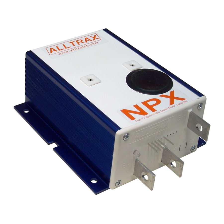
NPX Series Non-Programmable Motor Controller
Our NPX Series motor controllers are designed to be stock replacement controllers for stock cars only. With a peak current rating they are not designed for lifted or high performance vehicles. For a high performance controller order our AXE Series motor controllers. NPX controllers are not programmable and must be ordered for the exact car you are installing them in.
Safety Notes
 Alltrax recommends that all motor controller applications must have a fuse in the battery circuit. Failure to utilize a fuse will result in injury, property damage, and void all warranties. Approved fuses manufactured by Bussman or Littelfuse: Controllers rated at 400 amps (or less) use ANN250 Fuse. On controllers rated at 450 amps (or more) use ANN400.
Alltrax also recommends a diode across the coil of the solenoid (Cathode to Positive, Anode to Negative) if it is not already installed. A minimum of a 100V 1A diode (a 1N4004 is suitable) is required. See complete wiring diagrams for orientation.
Working on electric vehicles, sudden unexpected events can occur, it is recommended to:
- Place the drive axle on jack stands— wheels off the floor
- When working on wiring or batteries, always remove rings and watches and use the proper safety equipment, eye protection, and insulated tools
- Disconnect batteries before installing or working on the controller
LED Status Indicator
LED Blink Codes:
At power up, # of green blinks indicates configured throttle type:
1 Green = 0-5k
4 Green = EZ-GO inductive (ITS)
7 Green = CLUBCAR 5K-0, 3-wire
Normal display status:
Solid Green: Controller ready to run
Solid Red: Controller in programming mode
Solid Yellow: Controller throttle is wide open, controller is supplying max output, and is not in current limit.
Trouble Shooting
Error code display: # of RED blinks indicates any error conditions that might exist:
- Red = Throttle Position Sensor Over Range. Check for open wires.
- Red = Under Temperature. Controller below -25C
- Red = HPD. Throttle hasn't gone to zero during this power on cycle.
- Red = Over Temperature. Controller over 95C
- Red = unused
- Red = Battery Under Voltage detected. Battery V < under voltage slider
- Red = Battery Over Voltage detected. Battery V > over-voltage slider
Alltrax, Inc.
1111 Cheney Creek Rd
Grants Pass, OR. 97527
Phone: 541-476-3565
Fax: 541-476-3566
- Non-Programmable
- 300 and 400 Amp Peak
- 24 to 48 Volt DC
- For Series Motor
- Stock Vehicles Only
www.alltraxinc.com

Documents / ResourcesDownload manual
Here you can download full pdf version of manual, it may contain additional safety instructions, warranty information, FCC rules, etc.
Advertisement


Need help?
Do you have a question about the NPX and is the answer not in the manual?
Questions and answers