Table of Contents
Advertisement
Quick Links
Advertisement
Table of Contents

Related Manuals for AUDAC EPA254


Summarization of Contents
Safety and Precautions
Safety Instructions & Warnings
Essential safety instructions, handling, environment, and hazard warnings for operation.
Servicing & Compliance
Information on user-serviceable parts, qualified servicing, and EC Declaration of Conformity.
WEEE Disposal and Hazard Symbols
WEEE Disposal Guidelines
Instructions for proper disposal of electronic waste according to WEEE regulations.
Product Hazard Symbols
Explanation of internationally recognized symbols warning about potential electrical hazards.
Pin Connections and Wiring
Connection Standards
Adherence to international wiring standards for AUDAC audio equipment connections.
System Wiring Rules
Rules for wiring speaker cables and audio signal inputs for proper system functioning.
Front Panel Details
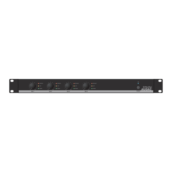
Front Panel Overview
Visual representation of the amplifier's front panel controls and indicators.
Front Panel Description
Detailed explanation of volume knobs, indicator LEDs, and the power switch.
Rear Panel Details
Rear Panel Overview
Visual representation of the amplifier's rear panel connections and switches.
Rear Panel Description
Details on AC power inlet, loudspeaker outputs, input connections, crossover, and operation mode switches.
Amplifier Connection Guide
Input Connections
How to connect signal inputs using balanced XLR connectors for each channel.
Output Connections
How to connect loudspeakers using terminal block connectors based on operation mode.
Transformer Connection Warning
Warning against direct connection with line transformers on loudspeaker outputs.
Amplifier Operation Modes
4-Channel Mode
Configuration for driving each channel with a separate input signal and individual loudspeakers.
2-Channel (Bridged) Mode
Merging two output channels for double power to a single load using bridge mode.
3-Channel (2-Way Sub/Top) Mode
3-Channel Configuration
Using crossover and bridge modes for stereo system with mono bass cabinet.
Technical Specifications
Output Power & Frequency Response
Detailed technical data including RMS output power, frequency response, and signal-to-noise ratio.
Inputs, Outputs, and Controls
Specifications for input/output connectors, impedance, sensitivity, and front panel controls.
Power Supply and Cooling
Details on power supply voltage range, amplifier technology, and cooling system.
Additional Technical Data
Power Consumption
Specifications for power consumption in standby, idle, and at rated power levels.
Dimensions and Weight
Physical dimensions (W x H x D), unit height, and weight for the amplifier models.
Need help?
Do you have a question about the EPA254 and is the answer not in the manual?
Questions and answers