Table of Contents
Advertisement
Quick Links
Advertisement
Table of Contents

Related Manuals for AUDAC APC100


Summary of Contents for AUDAC APC100
- Page 1 APC100 User Manual www.audac.eu...
-
Page 3: Table Of Contents
Waste of Electrical and Electronic Equipment (WEEE) Chapter 1: Connections and connectors Connection standards Chapter 2: Overview APC100 Front panel APC100 Rear panel APC100 Chapter 3: Configuring the APC100 Configuration interface Login screen Configuration screen Network settings Password settings Time settings... -
Page 5: Introduction
Introduction Universal configuration & control unit The APC100 is a configuration and control unit which can be used in combination with a wide variation of ‘smart’ AUDAC devices, ranging from matrix systems and mixers to paging consoles and wall panels. -
Page 6: Precautions
Precautions READ FOLLOWING INSTRUCTIONS FOR YOUR OWN SAFETY • ALWAYS KEEP THESE INSTRUCTIONS FOR FUTURE REFERENCE. NEVER THROW THEM AWAY • ALWAYS HANDLE THIS UNIT WITH CARE • CLEAN ONLY WITH DRY CLOTH • HEED ALL WARNINGS AND FOLLOW ALL INSTRUCTIONS •... -
Page 7: Caution Servicing
CAUTION • USE CABLES OF THE RIGHT GAUGE FOR CONNECTING LOUDSPEAKERS ON THE AMPLIFIED OUTPUTS • USE CABLES WITH CLEAR COLOUR CODING INDICATING THE POLARITY AND MAINTAIN THE SAME POLARITY THROUGHOUT THE WHOLE SYSTEM. • ONLY USE THE CORRECT LOAD IMPEDANCE (MIN 4 OHM) WHEN CONNECTING LOUDSPEAKERS ON THE AMPLIFIED OUTPUTS. -
Page 9: Chapter 1: Connections And Connectors
Chapter 1 Connections and connectors CONNECTION STANDARDS The in- and output connections for AUDAC audio equipment are performed corresponding to international wiring standards for professional audio equipment. RS232 (serial connection interface): For connection with home automation systems, or other remote control equipment... -
Page 11: Chapter 2: Overview Apc100
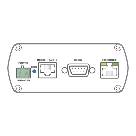
Overview APC100 Front panel APC100 APC100 Front panel Various control and configuration ports are located on the front panel of the APC100 together with the 24 Volts power connection. 1) 24 Volts power connector: 24 Volts DC mains power should be applied to this connector. Connect the wires of the included power supply (PSD241) here. -
Page 12: Rear Panel Apc100
The APC100 is equipped with an Ethernet network connection implemented using an RJ45 connector. The green and orange LED’s will indicate whether the network is connected and active. Using this port, the APC100 can be connected in any LAN network. -
Page 13: Chapter 3: Configuring The Apc100
Configuration interface Start your default web browser and enter the IP address of the embedded web server of the APC100 in the address bar. (The factory default IP address is http://192.168.0.194) Login screen First the login screen will be displayed. -
Page 14: Configuration Screen
Click the particular button if you want to make any changes to the corresponding settngs. Connection status At the top left position besides the ‘AUDAC’ logo is the connection status displayed. To have communication with the device, the connection status must show ‘ONLINE’. -
Page 15: Network Settings
Network Settings In this window, the network settings of the APC100 can be adjusted. The IP address is default set to 192.168.0.194 and the subnetmask is default set to 255.255.255.0. The settings can be changed by adjusting the parameters in the shown fields. -
Page 16: Password Settings
Password Settings In this window the password for the APC100 can be changed. Password settings screen for APC100 To change the password, enter the old password in the provided field and enter the new password twice in the fields below. After this is all completed, push the OK button. -
Page 17: Time Settings
In this window the time settings for the APC100 can be changed. Time settings screen for APC100 The current time and date for the APC100 can be set in this window. The APC100 act as a real-time-clock for synchronizing timer scheduled events on other devices connected in your network. -
Page 18: Address Settings
In this window the address settings for the APC100 can be changed. Address settings screen for APC100 In this window, the address for the APC100 can be selected. The address standard set to ‘001’ and selectable using the dropdown list within a range of ‘001’ and ‘099’. -
Page 19: Factory Settings
Factory Settings In the factory settings menu, all settings of the APC100 will be set to factory default. It does not recall the previously saved settings, but will recall the original factory settings and all previously made settings will be lost. -
Page 20: Chapter 4: Using The Apc100
Using as a gateway When the APC100 is being used as a gateway, it allows connection to and control through any TCP/IP based network for all devices containing an RS-232 or RS-485 interface with APC100 supported baudrate. (19200 baud). -
Page 21: Chapter 5: Additional Information
Many AUDAC products are controllable by Ethernet. The Ethernet connection which is used on the AUDAC products is TCP/IP based like 99% of the computer networks. There are some basics which you need to know to successfully make a TCP/IP Ethernet connection. - Page 22 You can change the IP address of the AUDAC products to make them work properly in your network. This can be done in the settings menu, and is described extensively in the “Settings” chapter of this user manual.
-
Page 23: Technical Specifications
Technical specifications Data connections Ethernet (RJ45) 2 x RS485 + Audio (RJ45) RS-232 (DB9) Power consumption < 1 Watt Power supply 24V DC PSD241 switching power supply included 100 ~ 240V AC / 47~63 Hz Dimensions (W x H x D) 108 x 44 x 96 mm Weight 0.73 Kg (Incl power supply) - Page 24 Notes...
Need help?
Do you have a question about the APC100 and is the answer not in the manual?
Questions and answers