
Related Manuals for Thermo King V-320 10


Summarization of Contents
Introduction
Revision History
Details changes made in the manual across different revisions.
General Information
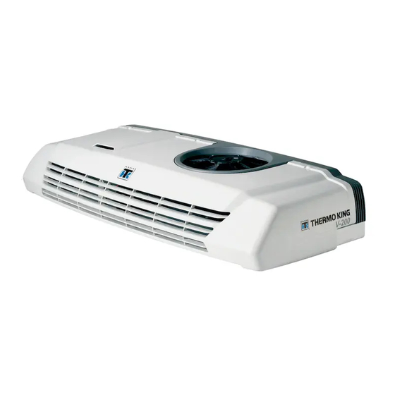
Covers unit models and lists related information for further reference.
Safety Precautions
Danger, Warning, Caution, and Notice
Defines safety advisories: Danger, Warning, Caution, and Notice.
General Practices
Provides general safety practices for handling refrigeration systems and equipment.
Auto Start/Stop
Safety precautions for starting and stopping the unit to prevent injury.
Battery Installation and Cable Routing
Safety warnings regarding battery installation, securing, and cable routing.
Refrigerant Oil Hazards
Safety precautions for handling refrigerant oil, including PPE and equipment care.
Electrical Hazards
Covers high voltage hazards, precautions, and risks associated with electrical systems.
Microprocessor Service Precautions
Precautions for preventing electrostatic discharge when servicing microprocessors.
Welding Precautions
Precautions to avoid damaging electronic components during welding.
First Aid
Provides first aid procedures for refrigerant, refrigerant oil, engine coolant, battery acid, electrical shock, and asphyxiation.
About This Manual
Purpose
Explains the manual's objective: to provide general maintenance information for climate control units.
Contents
Outlines the manual's chapter organization and the purpose of each chapter.
Before you Call Thermo King Service!
Provides information to have ready before contacting Thermo King service.
Blank Pages
Notes that blank pages may appear at the end of chapters and are normal.
Specifications
Electrical System
Details specifications for fuses, fan motors, solenoids, and coils.
Refrigeration System
Provides refrigerant charge and switch settings for R-134a and R-404A systems.
Compressors
Details specifications for engine driven, electric standby compressors, oil capacity, and clutch.
AC Electric Compressor Motors and Overload Relays
Lists specifications for AC motors, overload relays, including voltage, horsepower, and amps.
Contactors
Provides specifications for compressor motor contactors and electric heat contactors.
Capacitors
Lists capacitor types and provides safety warnings for handling them.
Transformer
Provides specifications for the transformer's power, frequency, inputs, and output voltage.
Start Relay (SR)
Details specifications for the start relay type, contacts, and coil resistance.
Electric Standby Power Supply Requirements
Lists requirements for electric standby power supply, including voltage, phase, breaker size, and cord length.
Optional Electric Heaters
Provides specifications for optional electric heaters, including voltage, power rating, current, and resistance.
Belt Tension
Specifies how to check belt tension for engine driven and electric standby compressors.
Solder Applications
Provides guidelines for solder application, joint clearances, and solder types for refrigeration tubing.
Unit Description
System Components Overview
Overview of key system components including condenser, evaporator, compressor, and control systems.
Refrigerant and Liquid Injection
Details refrigerants used and the liquid injection system for temperature control.
Evaporator Drain Line Heaters and Electric Standby
Details on evaporator drain line heaters and electric standby operation.
Unit Features
Lists standard and optional features of the refrigeration system.
Refrigeration System Components
Details refrigeration system components like solenoids, valves, switches, transducers, and control box elements.
Control Box Components
Covers P.C. Boards and the Electronic Control Module (ECM).
Unit Operation Modes
Describes unit operation modes: Cool, Null, Heat, and Defrost cycles.
Unit Operation
Explains how to operate the unit, including electric standby and programmable settings.
Cool Mode
Describes the operation of the unit in Cool Mode, including controller functions.
Cool Mode Model 10
Details the Cool Mode operation for Model 10, including refrigerant flow and solenoids.
Cool Mode Model 20 Engine Operation
Explains Cool Mode operation for Model 20, including refrigerant flow and components.
Cool Mode Model 20 Electric Standby Operation
Details Cool Mode operation for Model 20 electric standby, including refrigerant flow.
Cool Mode Model 30
Describes Cool Mode operation for Model 30, including refrigerant flow and solenoids.
Cool Mode Model 50 Engine Operation
Explains Cool Mode operation for Model 50 engine, including refrigerant flow and components.
Cool Mode Model 50 Electric Standby Operation
Details Cool Mode operation for Model 50 electric standby, including refrigerant flow.
Null Mode
Describes unit operation in Null Mode when setpoint temperature is reached.
Purge Mode – Model 30 and Model 50 Units Only
Explains Purge Mode operation for Models 30/50 before shifting to Heat mode.
Heat Mode - Model 30 and Model 50 Units Only
Describes Heat Mode operation for Models 30/50, including component energization.
Heat Mode Model 30
Details Heat Mode operation for Model 30, including refrigerant flow and solenoids.
Heat Mode Model 50 Engine Operation
Explains Heat Mode operation for Model 50 engine, including refrigerant flow.
Heat Mode Model 50 Electric Standby Operation
Details Heat Mode operation for Model 50 electric standby, including refrigerant flow.
Defrost Mode
Explains how defrost is initiated and continues until temperature rises or timer expires.
Defrost Mode Model 10
Details Defrost Mode for Model 10, including refrigerant flow and solenoid states.
Defrost Mode Model 20 Engine Operation
Explains Defrost Mode for Model 20 engine, including refrigerant flow.
Defrost Mode Model 20 Electric Standby Operation
Details Defrost Mode for Model 20 electric standby, including refrigerant flow.
Defrost Mode Model 30 and 50 Units
Compares Defrost Mode in Models 30/50 to Heat Mode, noting fan operation.
Serial Number Locations
Indicates the location of serial number nameplates on the condenser.
Unit Components Overview
Illustrates key unit components like the condenser and evaporator.
Maintenance Inspection Schedule
Electrical Maintenance Schedule
Schedule for electrical maintenance inspections: daily, weekly, 12/24 months or 2000/4000 hours.
Refrigeration/Heating Maintenance Schedule
Schedule for refrigeration/heating maintenance: daily, weekly, 12/24 months or 2000/4000 hours.
Structural Maintenance Schedule
Schedule for structural maintenance: daily, weekly, 12/24 months or 2000/4000 hours.
Electrical Maintenance
Electronic Control System
Refers to the Diagnostic Manual for service info on the microprocessor control system.
Defrost System
Details automatic/manual defrost initiation and termination based on timers and switches.
Defrost Termination Switch
Explains the function of the defrost termination switch and its temperature response.
Defrost Termination Switch Replacement
Provides step-by-step instructions for removing and installing the defrost termination switch.
Liquid Injection System (R-404A Units Only)
Explains the liquid injection switch function in R-404A units.
Testing Liquid Injection Solenoid Valve and Metering Orifice
Outlines the procedure for testing the LIS valve and metering orifice.
Liquid Injection Switch (LISW) Replacement
Provides removal and installation steps for the liquid injection switch (LISW).
Condenser Fan Motor
Notes non-repairable motors and provides current draw specs for maintenance.
Condenser Fan Motor Removal and Installation
Step-by-step instructions for removing and installing the condenser fan motor.
Evaporator Fan Motors
Notes non-repairable motors and provides current draw specs for maintenance.
Evaporator Fan Motor Removal and Installation
Step-by-step instructions for removing and installing evaporator fan motors.
Drain Line Heaters – DH1 and DH2
Explains the use of drain line heaters and how to check their operation.
Drain Line Heater Replacement
Provides removal and installation steps for drain line heaters.
Fuses
Identifies controller fuses and their amperage ratings.
Control Box Fuses
Identifies control box fuses and their amperage ratings.
Harness Fuses
Identifies fuses located in wiring harnesses outside the control box.
Relays
Describes relay types and provides testing procedures.
Relay Testing
Step-by-step guide for testing relays, checking continuity and voltage.
Relay Replacement
Provides steps for removing and installing relays.
Diode Assemblies
Explains LIS and BYPS diode assemblies and their functions.
Diode Assembly Testing
Details how to test diodes using a multimeter for continuity and resistance.
AC Components Model 20 and Model 50 Units Only
Highlights high voltage AC components used in electric standby operation.
Electrical Contactors
Explains how to test contact points and coils for contactors.
Compressor Motor Contactor – CMC
Describes the CMC contactor's function and replacement procedure.
Electric Heat Contactor – HC (Model 20 Option Only)
Details the HC contactor for electric heat option and its replacement.
Compressor Motor Overload Relay – OL
Explains the OL relay's function and the procedure for replacement and setup.
Compressor Motor Overload Relay Replacement
Provides steps for replacing the compressor motor overload relay.
Transformer – T1
Describes the transformer's function and testing procedure.
Transformer Testing
Step-by-step instructions for testing the transformer's AC voltage output.
Transformer Replacement
Provides removal and installation steps for the transformer.
Bridge Rectifier – BR
Explains the bridge rectifier's function and how to test it.
Capacitors
Lists capacitor types and provides safety warnings for handling them.
Capacitor Testing
Details procedures for testing capacitor health and capacitance value.
Capacitor Replacement
Provides steps for removing and installing capacitors, including discharge.
Start Relay – SR
Explains the start relay's function and provides testing procedures.
Start Relay Testing
Step-by-step guide for testing the start relay's operation and continuity.
Start Relay Replacement
Provides removal and installation steps for the start relay.
Compressor Motor
Includes testing procedures for compressor motors based on voltage and phase.
Testing 115/1/60 Units
Procedure for testing compressor motor operation on 115/1/60 units.
Testing 208-230/1/60 Units
Procedure for testing compressor motor operation on 208-230/1/60 units.
Compressor Motor Replacement
Step-by-step guide for removing and installing the compressor motor.
Electric Standby Circuits
Troubleshooting procedure for units not running in electric standby mode.
Heat Option – Truck Engine Coolant
Explains the truck engine coolant heat option and how to check its operation.
Heat Option – Truck Engine Coolant and Electric Standby Heater Strip
Details the electric standby heater strip option and its operational checks.
Refrigeration Maintenance
Maintenance Inspection Schedule
Schedule for refrigeration/heating maintenance inspections.
Evacuating and Charging the Refrigeration System
Explains procedures for evacuating and charging the refrigeration system.
Checking the Refrigerant Charge
Details how to inspect refrigerant charge via sight glass and pressure readings.
Testing the Refrigerant Charge with an Empty Box
Procedure for testing refrigerant charge with an empty box and specific pressure targets.
Testing the Refrigerant Charge with a Loaded Box
Procedure for testing refrigerant charge with a loaded box and checking sight glass.
Suction (Low Side) Bump Charging
Important procedure for charging the system with refrigerant to prevent compressor damage.
Checking Compressor Oil Charge
Procedure for ensuring adequate oil supply after refrigerant loss or removal.
Refrigeration System Checks
Basic checks for the refrigeration system, including manifold connection.
Cleanup Procedure for Small Truck Units
Detailed steps for cleaning the system after refrigerant contamination.
Putting the Unit Back Into Operation
Steps for reassembling and preparing the unit for operation after service.
Refrigeration Service Operations
Engine Driven Compressor Service
Procedures for removing and installing the engine driven compressor.
Electric Standby Compressor Service
Procedures for removing and installing the electric standby compressor.
Condenser Coil Service
Steps for removing and installing the condenser coil, including soldering.
Drier Service
Procedures for removing and installing the drier and sight glass.
Discharge Pressure Transducer (DPT) Service
Steps for removing and installing the DPT, including wire connection.
Hot Gas Solenoid (HGS) Test
Procedure for testing the hot gas solenoid by checking pressure and continuity.
Liquid Injection Solenoid (LIS) Test
Refers to Electrical Maintenance Chapter for LIS testing procedures.
Condenser Inlet Solenoid (CIS) Test
Details testing the CIS by checking temperatures, pressures, and continuity.
CPR Bypass Solenoid Test
Procedure for testing the CPR bypass solenoid by monitoring suction pressure.
Solenoid Valve Replacement
Provides steps for replacing solenoid valves, including heat sink use.
Oil Separator Service
Procedures for removing and installing the oil separator, including O-ring preparation.
Splice Fitting
Explains splice fitting use and important notes on metering orifice installation.
Liquid Injection Metering Orifice Service
Steps for removing and installing the liquid injection metering orifice.
Discharge Check Valve Service (Models 20/50)
Testing and replacement procedures for the discharge check valve.
Expansion Valve Assembly
Refers to another manual for check/adjustment of the expansion valve.
Checking Superheat
Procedure for checking superheat using gauges and thermometers.
Expansion Valve Replacement
Steps for removing and installing the expansion valve, including feeler bulb placement.
Low Pressure Cutout Switch (LPCO)
Explains the function of the LPCO switch and its pressure settings.
Low Pressure Cutout Switch Test
Procedure for testing the LPCO switch's operation based on suction pressure.
Low Pressure Cutout Switch Replacement
Provides removal and installation steps for the LPCO switch.
Suction Pressure Regulator Valve (Model 20 MAX Only)
Explains the SPR valve's purpose and adjustment for Model 20 MAX units.
Suction Pressure Regulator Valve Test
Procedure for testing the SPR valve by monitoring pressure and current draw.
Suction Pressure Regulator Valve Replacement
Steps for removing and installing the suction pressure regulator valve.
Compressor Pressure Regulator Valve (Model 30 and 50 Only)
Explains the CPR valve's function and adjustment for Models 30/50.
Compressor Pressure Regulator Valve Test
Procedure for testing the CPR valve by monitoring pressure and setting.
Compressor Pressure Regulator Valve Replacement
Steps for removing and installing the compressor pressure regulator valve.
Accumulator Service (Models 30/50)
Procedures for removing and installing the accumulator.
Liquid Line Check Valve Testing
Procedure for testing the liquid line check valve for opening and leaks.
Liquid Line Check Valve Replacement
Provides steps for replacing the liquid line check valve assembly.
Replacing Refrigerant Hoses (Speedy Clip System)
Refers to another manual for service info on replacing refrigerant hoses.
Compressor Maintenance
Compressor Failures
Guidance on checking compressor speed and pulley selection for failures.
Compressor Test
Detailed procedures for testing compressor function, including shaft rotation and air gap.
Belt Tensions
Importance of pulley alignment and belt tension for compressor installation.
Engine Driven Compressor Belt and Pulleys
Guidance on adjusting belt tension and checking pulley alignment.
Electric Standby Compressor Belt
Instructions for adjusting belt tension on the electric standby compressor motor.
Structural Maintenance
Maintenance Inspection Schedule
Schedule for structural maintenance inspections: daily, weekly, 12/24 months.
Condenser and Evaporator Coils
Guidance on cleaning coils, removing debris, and repairing bent fins.
Coil Cleaning Procedures
Recommendations for coil cleaning intervals and methods, including safety precautions.
Unit Mounting Bolts
Instructions to periodically check and torque unit mounting bolts.
Need help?
Do you have a question about the V-320 10 and is the answer not in the manual?
Questions and answers