Table of Contents
Advertisement
Quick Links
OPERATING MANUAL
UK
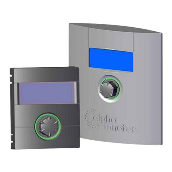
Heating- and heat pump control
Part 2
LUXTRONIK
Scope of delivery, Montage,
Electrical connections,
Installation of sensors, Dismantling
Software update
Switching on / Commissioning
Program area "Cooling"
Program area "Service"
Program area "Parallel mode"
Appendix
83055400kUK – 2.1
www.alpha-innotec.com
Advertisement
Table of Contents

Summarization of Contents
Introduction and Safety Information
Please Read First
Crucial preliminary information and warnings for safe operation.
Symbols Guide
Explanation of all warning symbols and icons used throughout the manual.
Installation and Initial Setup
Scope of Delivery
Details the components included with the heating and heat pump controller.
Montage and Wall Control Installation
Instructions for physically mounting the control unit and associated hardware.
Electrical Connections
Wiring guidelines for connecting the unit and external components.
Sensor Installation
Procedures for installing external and hot water sensors correctly.
Dismantling Procedures
Steps for safely removing the heating and heat pump control unit.
Commissioning and Basic Operation
Software Updates and Downgrades
Process for updating unit software via USB interface.
Switching On and Commissioning
Initial startup, self-test, language selection, and hydraulic code entry.
Startup Guide and Parameter Configuration
Step-by-step assistant for essential initial system settings.
Startup Parameter Management
Saving, loading, and resetting system startup parameters.
Emergency Mode Operation
How the system operates in emergency mode and its conditions.
Program Area: Cooling
Selecting and Setting Up Cooling Mode
Activating and configuring the cooling function and its operation modes.
Cooling Temperature and Parameter Settings
Adjusting temperature setpoints, hysteresis, and control parameters for cooling.
Cooling Control Logic and Enablement
Managing cooling based on set temperature or outdoor conditions.
Program Area: Service and System Information
Service Area Navigation
Accessing the service program area for advanced functions.
Querying System Information (Temperatures, Inputs, Outputs)
Retrieving data on system temperatures, inputs, and outputs.
Querying Operational Data (Times, Errors, Status)
Accessing elapsed times, operating hours, error logs, and system status.
Energy Monitoring and Historical Data
Tracking energy consumption and viewing historical performance data.
Specialized Queries (Smart, Inverter, EventLog, InfoLog)
Accessing specific data logs for smart features, inverter, events, and errors.
System Settings and Configuration
Data Access and Parameter Adjustment
Managing access levels and adjusting system parameters.
Temperature Settings and Priorities
Configuring temperature setpoints, hysteresis, and operational priorities.
Hot Gas Utilisation and System Settings
Adjusting hot gas settings and other core system configurations.
Mixing Circuits and DHW Configuration
Setting up mixing circuits and domestic hot water preparation options.
Screed Heating Program Setup
Configuring the automatic screed floor heating sequence.
Heat Pump Configuration and Control Panel Settings
Customizing heat pump features and control panel display.
Advanced Features: Networking, Smart Control, and Parallel Operation
FlexConfig and Silent Mode Operation
Customizing outputs and enabling low-noise operation modes.
Pump Flow Lead Time, Smart Home, and Smart Grid
Configuring pump timings, smart home integration, and smart grid functions.
Parallel Mode Operation Basics
Understanding parallel mode and its application with multiple heat pumps.
Network Configuration and IP Addressing
Configuring network settings for parallel heat pump communication.
Master Unit Configuration and Slave Management
Setting up the master unit and managing connected slave heat pumps.
Troubleshooting and Technical Information
Error Diagnosis and Message Interpretation
Detailed list of error codes, their causes, and remedies.
Fault Acknowledgement and Controller Board Codes
Procedures for handling errors and understanding LED status codes.
Technical Data and Specifications
Overview of electrical data, sensor curves, and interface details.
Sensor Measuring Ranges and Operational Overviews
Sensor limits and summaries of defrost cycles and flow max.
System Setting During Commissioning Parameters
Comprehensive table of adjustable parameters for initial setup.
Abbreviations and Glossary
Definitions of technical terms and abbreviations used in the manual.


Need help?
Do you have a question about the LUXTRONIK LWAV 122R3 and is the answer not in the manual?
Questions and answers