
Related Manuals for Alpha-InnoTec Hydraulic Module 2


Summary of Contents for Alpha-InnoTec Hydraulic Module 2
- Page 1 Accessories for two Dual Air / Water Heat Pumps Operating Manual Hydraulic Module 2 HMD 2/(S)E HMD 2/R(S)E 83055500cUK – Translation of the original operating manual...
-
Page 2: Please Read First
Please read first Symbols This operating manual provides important information The following symbols are used in the operating man- on handling the unit. It is an integral part of the product ual. They have the following meaning: and must be kept ready to hand in the immediate vicin- ity of the unit. -
Page 3: Table Of Contents
Contents Please read first ............2 Technical data/Scope of supply HMD 2/(S)E ............18 Symbols ..............2 HMD 2/R(S)E ............. 19 Intended use .............. 4 Free pressure ............20 Disclaimer ..............4 Dimensioned drawings Safety and Security ........... 4 HMD 2/(S)E ............21 Contact .............. -
Page 4: Intended Use
Intended use Safety and Security The hydraulic module is a functionally relevant acces- The unit is safe to operate for its intended use. The sory for dual air/water heat pumps intended for out- construction and design of the unit conform to current door installation. -
Page 5: Contact
A WME (heat metering) only has to be installed for brine/water and water/water heat pumps ● Germany: www.alpha-innotec.de for a flow temperature ≥35 °C. The WME must record ● www.alpha-innotec.com the total thermal energy output (heating and hot water) in the building. -
Page 6: Care Of The Unit
Care of the unit Scope of supply The outer surfaces of the unit can be cleaned with a damp cloth and standard cleaning products. Do not use cleaning or care products that contain abrasives, acids and/or chlorine. Such products would destroy the surfaces and could also damage the tech- nical components of the unit. -
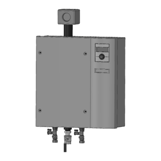
Page 7: Components Of The Unit
Check the scope of supply for completeness. Reversible variant: HMD 2/R(S)E Any defects or incorrect deliveries must be report- ed immediately. NOTE Note the unit model. “Technical Data / Scope of Supply” overview from Page 18 or rating plate on the unit. Components of the unit 2 versions of the hydraulic module are available: HMD 2/(S)E... -
Page 8: Installation
Installation Installation 2 people are needed to lift the hydraulic module The following applies to all work to be done: out of the box. Undo the quick-release screws in the top section NOTE of the hydraulic module and remove the top sec- Always comply with the applicable local acci- tion from the front. -
Page 9: Unit Lettering / Labelling
Unit lettering / labelling ● Vertically perforated (honeycomb) bricks ● Hollow floors/ceilings made of clay bricks, con- Before making the hydraulic and electrical connection crete or similar you must label the two heat pumps outdoors and their ● Solid gypsum boards connection cables. -
Page 10: Installation / Hydraulic Connection To Heating Circuit
Installation / Hydraulic connection Calculate the hydraulics of your system in accord- ance with the schematic on Page 27 . to heating circuit Flush the heating circuit thoroughly before con- Pressure loss calculation necting the unit to the heating circuit. NOTE NOTE There are two circulation pumps integrated in... -
Page 11: Safety Assembly
HMD 2/R(S)E The safety assembly for the heating circuit is pre-in- stalled. ATTENTION Perform leak test on the piping. Take the insulation half-shells from the enclosed separate package and insulate the adapter from the hydraulic module to the safety assembly. 1 Flow inlet, heat pump 1 2 Flow inlet, heat pump 2 3 Flow outlet, heat pump 1 and 2... -
Page 12: Electrical Connections
Electrical connections 400 V / 230 V operation The hydraulic module is compatible with heat The following applies to all work to be done: pumps for the 3~400V power supply system (3~N/ PE/400V/50Hz) and with heat pumps for the 1~230V DANGER power supply system (1~N/PE/230V/50Hz). -
Page 13: Electrical Connection Of The Heat Pumps To The Hydraulic Module
Electrical connection of the heat pumps to the hydraulic module 2x F New jumpers to be set for operation in the 1~230V power supply system 3 Jumper between 1L1 and 1L2 4 Jumper between 1L2 and 1L3 ATTENTION Example HMD 2/(S)E: This termination is only allowed if the hydraulic 1 230 V inputs module is operated in the 1~230V power supply... - Page 14 Connect LINBus cable of heat pump 1 to termi- Unshielded power supply cables (power sup- nal strip -X1. ply of outdoor units) and shielded cables (LIN- Bus) must be laid with the following minimum distances between them: without separator ≥ 50 mm separator made of aluminium ≥...
-
Page 15: Flushing, Filling And Bleeding The System
Seal the cable penetrations for cables, which are Turn the stem through 180° and flush the hot wa- routed from the heat pumps into the buildings, in ter charging circuit for approx. 1 minute. the outdoor area. Turn the spindle 180° back to its starting position (rounded side of the stem points to B). -
Page 16: Set The Overflow Valve
Set the overflow valve Commissioning Follow the instructions in the section entitled REMARQUE “Commissioning” in the operating manual for your The activities in this section are only neces- heat pump. sary for in-line tank integration. Complete the worksteps quickly, otherwise the Safety temperature limiter maximum return temperature can be exceeded and the heat pump switches to high-pressure... -
Page 17: Dismantling
Dismantling HMD 2/R(S)E DANGER Risk of fatal electric shock! All electrical work must be carried out by qualified electricians only. Before opening the unit, disconnect the system from the power supply and prevent it from being switched back on! WARNING Only qualified heating or cooling system technicians are allowed to remove the unit from the system. -
Page 18: Technical Data/Scope Of Supply
Technical data/Scope of supply HMD2/(S)E Unit designation Accessories for LWD 50A - LWD 70A - LWD 90A - LWD 50A/SX - LWD 70A/SX • • applicable ı — not applicable Heat pump type LWD 50A/RX - LWD 70A/RX - LWD 50A/RSX - LWD 70A/RSX —... -
Page 19: Hmd2/R(S)E
HMD2/R(S)E Unit designation Accessories for LWD 50A - LWD 70A - LWD 90A - LWD 50A/SX - LWD 70A/SX — • applicable ı — not applicable Heat pump type LWD 50A/RX - LWD 70A/RX - LWD 50A/RSX - LWD 70A/RSX •... -
Page 20: Free Pressure
HMD 2/… Free pressure pmax “” [m 812036 Legende: “v” Volumenstrom Heizwasser in m /h je Pumpenzweig, zwei Zweige verfügbar pmax maximale freie Pressung Keys: UK812036 Heating water volume flow in m³/h per pump branch, two branches available “” ∆pmax maximum free pressure Subject to change without notice | 83055500cUK –... -
Page 21: Dimensioned Drawings
Dimensioned drawings HMD 2/(S)E Keys: UK819439 All dimensions in mm. Front view Side view from right The hydraulic module is installed in the heating flow! Pos. Designation Dim. Control element Legende: D819439 Das Hydraulikmodul wird im Heizungsvorlauf Penetrations for electric/sensor cables Alle Maße in mm. -
Page 22: Hmd 2/R(S)E
HMD 2/R(S)E Dimensioned drawings Keys: UK819440 All dimensions in mm. Front view Side view from right The hydraulic module is installed in the heating flow! Pos. Designation Dim. Legende: D819440 Das Hydraulikmodul wird im Heizungsvorlauf Control element Alle Maße in mm. installiert! Penetrations for electric/sensor cables Vorderansicht... -
Page 23: Drilling Pattern
Drilling pattern HMD 2/… Keys: UK819443 All dimensions in mm. Legende: D819443 Hole Ø 12 for anchor (enclosed in separate package) Alle Maße in mm. Bohrung 12 für Dübel (im Beipack) Pos. Designation Wall mounting rail (in separate package) Sheet metal housing Subject to change without notice | 83055500cUK –... -
Page 24: Installation Plans
HMD 2/(S)E Installation plan >1350 >200 >600 Keys: UK819441 Legende: 819441 All dimensions in mm. Alle Maße in mm. OKF Oberkante Fertigfussboden Pos. Designation Freiraum für Servicezwecke Top edge of finished floor Free space for service purposes Zust. Änderun Subject to change without notice | 83055500cUK – Translation of the original operating manual | ait-deutschland GmbH... -
Page 25: Hmd 2/R(S)E
Installation plan HMD 2/R(S)E >1350 >200 >600 Keys: UK819442 Legende: 819442 All dimensions in mm. Alle Maße in mm. Pos. Designation OKF Oberkante Fertigfussboden Top edge of finished floor Freiraum für Servicezwecke Free space for service purposes Subject to change without notice | 83055500cUK – Translation of the original operating manual | ait-deutschland GmbH... -
Page 26: Calculation Example
Calculation example Volume flows (V1 / V2) heat pump T1 LWD 50A V in m³/h 21.820 Pa T1 / T2 Vmin Vnom Vmax 0,22 bar A1 HVLD 3m AV1 1.200 l/h LWD 50A/… 1200 1500 D1 3.000 Pa LWD 70A/… 1200 1600 2000... -
Page 27: Calculation Of Your System
Calculation of your system 0 Pa 10. Add the inherent pressure losses in the calcula- Complete all fields and table rows marked with an asterisk *). tion tables to the pressure loss of heat pump 1 In the grey field T1, enter the type of your heat and to the pressure loss of heat pump 2. -
Page 28: Flushing And Venting Process, Hot Water Circuit
Flushing and venting process, hot water circuit ATTENTION Changeover valve (BUP) must be open in the direc- tion of the hot water circuit. VL HW RL HW RL WW Keys: VL HW Heating water flow Heat pump RL WW Hot water return Safety valve Shut-off valve closed Pressure gauge... -
Page 29: Flushing And Venting Process, Heating Circuit
Flushing and venting process, heating circuit ATTENTION Changeover valve (BUP) must be open in the direc- tion of the heating circuit. VL HW RL HW RL WW Keys: VL HW Heating water flow Heat pump RL WW Hot water return Safety valve Shut-off valve closed Pressure gauge... -
Page 30: Flushing And Venting Process, Heat Pump 1
Flushing and venting process, heat pump 1 VL HW RL HW RL WW Keys: VL HW Heating water flow Heat pump RL WW Hot water return Safety valve Shut-off valve closed Pressure gauge Shut-off valve open Hot water changeover valve (BUP) Wall penetration Wall bracket Outdoor sensor... -
Page 31: Flushing And Venting Process, Heat Pump 2
Flushing and venting process, heat pump 2 VL HW RL HW RL WW Keys: VL HW Heating water flow Heat pump RL WW Hot water return Safety valve Shut-off valve closed Pressure gauge Shut-off valve open Hot water changeover valve (BUP) Wall penetration Wall bracket Outdoor sensor... -
Page 32: Hydraulic Integration Row Tank
HMD 2/… Row tank Subject to change without notice | 83055500cUK – Translation of the original operating manual | ait-deutschland GmbH... -
Page 33: Separate Buffer Tank And Unit Variant R (Cooling)
Separate buffer tank and HMD 2/… unit variant R (cooling) Subject to change without notice | 83055500cUK – Translation of the original operating manual | ait-deutschland GmbH... -
Page 34: Legend Hydraulic Integration
Subject to change without notice | 83055500cUK – Translation of the original operating manual | ait-deutschland GmbH... - Page 35 Subject to change without notice | 83055500cUK – Translation of the original operating manual | ait-deutschland GmbH...
-
Page 36: Schematic Diagram Of The Electrical Connections
Schematic diagram of the electrical connections Z-VD 1 Z-VD 2 Z-HS Z-ST HWE-1 HWE-2 (VL) ATTENTION When laying the cable, note that unshielded power supply cables (power supply of outdoor units) and shielded cables (LINBus) must be laid separately from each other. ... -
Page 37: Terminal Diagrams 400V: Lwd
Terminal diagram 400V: LWD … / HMD 2/… 1~N/PE/230V/50Hz 3~N/PE/400V/50Hz 3~N/PE/400V/50Hz 3~N/PE/400V/50Hz X8-1 X10⁻¹ LIN-1 X8-2 X10⁻² Lin-2 OUT8 OUT7 OUT6 OUT5 OUT4 OUT3 OUT2 OUT1 NTC1 GND1 NTC2 GND2 NTC3 GND3 NTC4 GND4 NTC5 TRL ext. GND5 NTC6 GND6 NTC7 GND7 NTC8... -
Page 38: 230V: Lwd
230V: LWD ... / HMD 2/… Terminal diagram 1~N/PE/230V/50Hz 1~N/PE/230V/50Hz 1~N/PE/230V/50Hz 1~N/PE/230V/50Hz X7-1 X10⁻¹ LIN-1 X7-2 X10⁻² Lin-2 OUT8 OUT7 OUT6 OUT5 OUT4 OUT3 OUT2 OUT1 NTC1 GND1 NTC2 GND2 NTC3 GND3 NTC4 GND4 NTC5 TRL ext. GND5 NTC6 GND6 NTC7 GND7 NTC8... - Page 39 Circuit diagram 1/3 HMD 2/… Subject to change without notice | 83055500cUK – Translation of the original operating manual | ait-deutschland GmbH...
- Page 40 HMD 2/… Circuit diagram 2/3 Subject to change without notice | 83055500cUK – Translation of the original operating manual | ait-deutschland GmbH...
-
Page 41: Circuit Diagrams
Circuit diagram 3/3 HMD 2/… OUT1 yellow white AIN1 Green AGND1 Brown AOUT1 yellow white AIN2 Green AGND2 Brown AOUT2 NTC6 GND6 NTC7 GND7 NTC8 GND8 NTC9 GND9 Subject to change without notice | 83055500cUK – Translation of the original operating manual | ait-deutschland GmbH... - Page 42 Subject to change without notice | 83055500cUK – Translation of the original operating manual | ait-deutschland GmbH...
-
Page 43: Ec Declaration Of Conformity
EC Declaration of Conformity The undersigned confirms that the following designated device(s) as designed and marketed by us fulfill the standardized EC directives, the EC safety standards and the product-specific EC standards. In the event of modification of the device(s) without our approval, this declaration shall become invalid. Designation of the device(s) Heat Pump Unit model... - Page 44 GmbH Industriestrasse 3 95359 Kasendorf, Germany E info@alpha-innotec.de W www.alpha-innotec.de alpha innotec – an ait-deutschland GmbH brand...
Need help?
Do you have a question about the Hydraulic Module 2 and is the answer not in the manual?
Questions and answers