Table of Contents
Advertisement
Quick Links
Advertisement
Table of Contents

Related Manuals for Alpha-InnoTec Hydraulic tower HT7


Summary of Contents for Alpha-InnoTec Hydraulic tower HT7
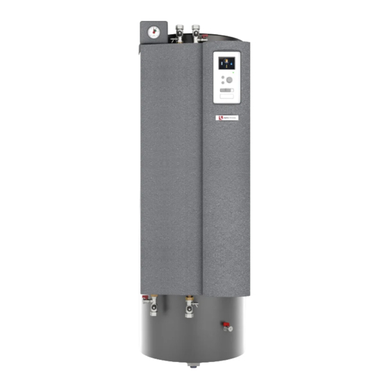
- Page 1 Accessory for heat pumps Operating Manual Hydraulic tower HT 7 83070100bUK...
-
Page 2: Table Of Contents
Contents 12 Overflow valve About this operating manual ..........18 ...... 3 Validity ............3 13 Volumetric flow meter / Heat meter ..19 Reference documents ....... 3 14 Malfunctions ..........19 Contact ............4 14.1 Unlocking the safety temperature limiter 19 Safety ............... 4 14.2 Alarm ............19 Intended use .......... -
Page 3: About This Operating Manual
About this operating manual Symbols and markings This operating manual is part of the unit. Identification of warnings ► Before working on or with the unit, always read Symbol Meaning the operating manual carefully and follow it for all activities at all times, especially the warnings and Safety information. -
Page 4: Contact
Children must not play with the product. ● Germany: www.alpha-innotec.de The product may only be opened by qualified special- ● www.alpha-innotec.com ist personnel. All procedural instructions in this operating manual are solely directed at qualified specialist personnel. -
Page 5: Residual Risks
2.4 Residual risks Impact of low-quality filling and top-up water in the heating circuit Injuries caused by electric shock The quality of the heating water is crucial for the effi- ciency of the system and the service life of the heat Components in the unit are energised with life-threat- generator and the heating components. ening voltage. Before working on the unit: If the system is filled with untreated drinking water, cal- ►... -
Page 6: Scope Of Supply
Scope of supply 4.2 Components of the unit Example of Scope of supply packaging: 1 Compact unit (domestic hot water tank and buffer tank, without heat pump) 2 Separate package: Control panel of the heating and heat pump controller HPC, safety assembly, pump ball valves, indoor/outdoor temperature sensor RS (Split), adjustable feet, 1 Shut-off ball valve with drain tap 230V connecting bridge ( “Terminal diagram 2 Shut-off ball valve with filling and drain tap 1/2”, page 25) -
Page 7: Storage, Transport And Installation
Storage, transport and 5.2.2 Unpacking installation Remove the plastic films. Ensure that you do not damage the unit in the process. 5.1 Storage Dispose of the transport and packaging material in an environmentally-friendly manner and in ac- ► Store the unit so that it is protected against: cordance with local regulations. ●... -
Page 8: Transport With Handcart
Disconnect the domestic hot water temperature sen- sor (BT6) inside the switch box and withdraw the sensor cable out of its grommet in the switch box. Opening and closing the switch box: „7.2 Electrical connection“, page 13 Terminals for the domestic hot water temperature sensor: ... -
Page 9: Installation
5.5 Installation IMPORTANT When mounting the hydraulic system, insert the ca- ble of the domestic hot water temperature sensor Installation site through its grommet into the support plate. Take care not to damage the cable. IMPORTANT 7.2. Install the unit inside buildings only. The installation area must be frost-free and dry. -
Page 10: Hydraulic Connection To Heating Circuit And Domestic Hot Water
Hydraulic connection to heating Feed the cable of the domestic hot water temper- ature sensor (BT6) through its grommet into the circuit and domestic hot water switch box and connect it. Opening and closing the switch box: IMPORTANT „7.2 Electrical connection“, page 13 Dirt and deposits in the hydraulic (existing) system Terminals for the domestic hot water temperature can lead to damage to the unit. -
Page 11: Heating Circuit
6.1 Heating circuit 6.2 Expansion vessel The expansion vessel for the heating circuit is inte- Safety assembly and shut-off ball valves grated. Always check whether the expansion vessel is large Remove the safety assembly and shut-off ball enough for the system. If necessary, an additional ex- valves from the separate package and install them pansion vessel must be installed on site according to on the connections provided for this purpose. -
Page 12: Electrical Installation
Electrical installation IMPORTANT Moisture must no be trapped in the housing. If nec- essary, completely drain the inside of the housing be- IMPORTANT fore installing the housing cover. An incorrect rotating field will cause irreparable dam- Make sure that the housing is leaktight as a result age to the compressor. of the zero potential installation and that water can- not penetrate the housing at any time (for example, ►... -
Page 13: Electrical Connection
7.2 Electrical connection Route the sensor cable to the electrical switch box of the hydraulic tower HT 7. The electrical connection is established via the electri- Connect the sensor cable as BT 50 (room sensor) cal switch box. according to the terminal diagram. Insert the control and sensor cables, the load and ... - Page 14 Secure all cables inserted into the switch box with BT1 Hydraulic tower HT 7 strain relief in the electrical switch box and route plug-in connections for the control panel out of the opening (③) in the front cover of the electri- cal switch box.
-
Page 15: Installing The Control Panel
Installing the control panel Dismantling the control panel Insert the small slotted screwdriver from above in- Remove the control panel from the separate pack- to the upper lock (③) and press on the handle in age and hang it on its 3 hooks in the switchgear the direction of the control panel until the lock of compartment panel. -
Page 16: Flushing, Filling And Venting
Flushing, filling and venting 9.2 Flushing and filling the heating and domestic hot water charging 9.1 Heating water quality circuit The outlet pipe of the safety valve must be con- NOTE nected. ● For detailed information, see also the ► Ensure that the set pressure of the safety valve is VDI Guidelines 2035 "Vermeidung von not exceeded. -
Page 17: Flushing, Filling And Venting The Domestic Hot Water Tank
Pull the valve motor (③) forward carefully from the 11. Insert the U-clip (②) on the rear of the valve mo- 3-way switching valve (④). tor (③). Turn the spindle of the 3-way switching valve so that the rounded side of the spindle points to- wards marking A of the connections of the 3-way 12. -
Page 18: Insulating Hydraulic Connections
10 Insulating hydraulic 12 Overflow valve connections The overflow valve adjustment procedure should be performed as follows during system startup: Insulate hydraulic lines in accordance with local regu- Open the overflow valve (➀) completely. lations. Turn the adjusting knob (②) on the overflow valve Open shut-off devices. to the right to increase the temperature difference Perform a pressure test and check for leaks. (the temperature drop), and turn it to the left to re- duce it. -
Page 19: Volumetric Flow Meter / Heat Meter
13 Volumetric flow meter / 14 Malfunctions Heat meter 14.1 Unlocking the safety temperature The integrated volumetric flow meter / heat meter (①) limiter is used to measure the heat quantity generated by the heating system and made available for domestic hot A safety temperature limiter is installed in the electri- water preparation and building heating. -
Page 20: Emergency Operation
15 Dismantling and disposal 14.3 Emergency operation Heating and heat pump controller HPC operating 15.1 Dismantling manual, “Comfort malfunction” section ► Separate components by their materials. Thermostat for emergency operation 15.2 Disposal and recycling In emergency operation, the flow temperature is set via the electric heating element thermostat (①) ac- ►... -
Page 21: Technical Data / Scope Of Supply
Technical data / Scope of supply Accessories for heat pump type Hydraulic tower HT 7 Air/water output-controlled Indoor and outdoor installation 4 kW | 8 kW | 12 kW • yes – no – | – | – Air/water dual output-controlled Outdoor installation 9 kW •... -
Page 22: Performance Curves
Hydraulic tower HT 7 Free compression Δpmax Δp “ ” [m Key: UK823324 Key: UK823324 “” “” Volume flow heating water Volume flow heating water ∆pmax ∆pmax maximum free pressure maximum free pressure 823284 Legende: “” Volumenstrom Heizwasser in m ∆pmax maximale freie Pressung Subject to technical amendments without prior notice | 83070100bUK | ait-deutschland GmbH... -
Page 23: Dimensional Drawings
Dimensional drawings Hydraulic tower HT 7 226 83 <1800 1651 1517 1163 97 180 Key: UK819525 All dimensions in mm. Item Name Dim. Front view Side view from the left Rear view Safety assembly Heating water inlet (return) Rp 1″ internal thread Heating water outlet (supply) Rp 1″ internal thread Control panel Draining for buffer tank G 1/2″... -
Page 24: Installation Plans
Hydraulic tower HT 7 Installation plans >1200 >100 >500 Legende: 819526- Alle Maße in mm. Key: UK819516 OKF Oberkante Fertigfussboden All dimensions in mm. Freiraum für Servicezwecke Item Name Free space for service purposes OKF Top edge of finished floor Technische Änderungen vorbehalten. Subject to technical amendments without prior notice | 83070100bUK | ait-deutschland GmbH... -
Page 25: Terminal Diagrams
Terminal diagram 1/2 Hydraulic tower HT 7 Refer to protection notice ISO 16016. Subject to technical amendments without prior notice | 83070100bUK | ait-deutschland GmbH... - Page 26 Hydraulic tower HT 7 Terminal diagram 2/2 3G1,5mm² 4x0,75mm² 3x0,75mm² 2x0,75mm² BT50 +MR1 2x0,75mm² 1x1,5mm² Refer to protection notice ISO 16016. Subject to technical amendments without prior notice | 83070100bUK | ait-deutschland GmbH...
- Page 27 Terminal diagrams key Hydraulic tower HT 7 UK 831241a Refer to protection notice ISO 16016. Subject to technical amendments without prior notice | 83070100bUK | ait-deutschland GmbH...
-
Page 28: Circuit Diagrams
Hydraulic tower HT 7 Circuit diagram 1/2 Direct connection /1.2 Switch box /2.2 Direct connection +MR1 Switch box X2_3 / 2.9 X3_3 / 2.8 Refer to protection notice ISO 16016. Subject to technical amendments without prior notice | 83070100bUK | ait-deutschland GmbH... - Page 29 Circuit diagram 2/2 Hydraulic tower HT 7 +MR1 X1_L_3 / &EFZ/2.8 X1_N1_3 / 1.8 X1_N2_1 / &EFZ/2.9 X1_PE1_3 / &EFZ/2.9 +MR1 Direct connection Refer to protection notice ISO 16016. Subject to technical amendments without prior notice | 83070100bUK | ait-deutschland GmbH...
- Page 30 Hydraulic tower HT 7 Circuit diagrams key UK 817465a Refer to protection notice ISO 16016. Subject to technical amendments without prior notice | 83070100bUK | ait-deutschland GmbH...
- Page 31 Subject to technical amendments without prior notice | 83070100bUK | ait-deutschland GmbH...
- Page 32 GmbH Industriestraße 3 D-95359 Kasendorf E info@alpha-innotec.de W www.alpha-innotec.de alpha innotec – an ait-deutschland GmbH brand...
Need help?
Do you have a question about the Hydraulic tower HT7 and is the answer not in the manual?
Questions and answers