Table of Contents
Advertisement
Quick Links
Installation and
Montage- und
operating manual
Bedienungsanleitung
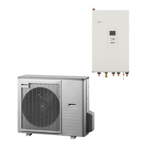
HM 6Split
HM 6Split
HM 12Split
HM 12Split
Accessory for
Zubehör für
air / water
Wasser-Systeme vom
split heat pumps
Typ Split
18–03–2021
30109
18.03.2021
Subject to change without notice | 83025900cUK | ait-deutschland GmbH
30108
Technische Änderungen vorbehalten | 83025900cDE | ait-deutschland GmbH
Advertisement
Table of Contents

Related Manuals for Alpha-InnoTec HM 6Split


Summary of Contents for Alpha-InnoTec HM 6Split
- Page 1 Installation and Montage- und operating manual Bedienungsanleitung HM 6Split HM 6Split HM 12Split HM 12Split Accessory for Zubehör für air / water Wasser-Systeme vom split heat pumps Typ Split 18–03–2021 30109 18.03.2021 Subject to change without notice | 83025900cUK | ait-deutschland GmbH 30108 Technische Änderungen vorbehalten | 83025900cDE | ait-deutschland GmbH...
-
Page 3: Table Of Contents
9 Control ___________________ 39 3 Design of the indoor unit _______ 8 Menu 1 - INDOOR CLIMATE ________________ 39 HM 6Split / HM 12Split ___________________ 8 Menu 2 - HOT WATER ____________________ 40 Dimensions and pipe connections ___________ 10 Menu 3 - INFO _________________________ 40... -
Page 4: Important Information
This appliance can be used by Marking children aged 8 years and above HM 6Split / HM 12Split is CE marked and persons with reduced phys- and has an IP21 protection rating. ical, sensory or mental capacity... - Page 5 Connecting communication Perimeter protection Protection, indoor unit Building protection Outdoor temperature sensor Room sensor Current sensor Safety circuit breaker Residual-current device Setting the thermostat to emer- gency mode Miscellaneous Docked to HM 6Split Section 1 | Important information HM 12Split...
-
Page 6: Delivery And Handling
• HM 6Split - unit dedicated for use with L 6Split. CAUTION The HM 6Split / HM 12Split unit must be hanged on • HM 12Split - unit dedicated for use with L 8Split the wall using the included hanger. The device can be and L 12Split. -
Page 7: Installation Location
Installation location Supplied components HM 6Split / HM 12Split can be installed in any room • Hanger (1 pc.) protected against temperature drop below 0°C to • Safety group (1 pc.) avoid freezing of the heating medium. 800 mm of •... -
Page 8: Design Of The Indoor Unit
3 Design of the indoor unit HM 6Split / HM 12Split XL11 AA23 AA2:X4 BT30 K1A-K3A AA27 AA2:X15 AA2:X4 XL10 XL13 XL14 BT12 BT63 BT25 BT71 BT15 QN10 GP12 Section 3 | Design of the indoor unit HM 6Split HM 12Split... - Page 9 Rear left cable groomet Rear right cable groomet Lower left cable groomet Lower right cable groomet Nameplate Plate with the designation of the hydraulic connections Serial number Software serial number HM 6Split Section 3 | Design of the indoor unit HM 12Split...
-
Page 10: Dimensions And Pipe Connections
XL13 XL14 Pipe connections Connection, heating medium supply, Ø22 mm for HM 6Split and HM 12Split, Connection, heating medium return, Ø22 mm for HM 6Split and HM 12Split, Connection, HW heating medium supply, Ø22 mm for HM 6Split and HM 12Split, XL10 Connection, GW1/2”... -
Page 11: Pipe Connections
5 m. The HM 6Split / HM 12Split unit can be docked to the central heating, cooling operation and hot water sys- tems. It is absolutely necessary to install the safety assembly on connection XL11. - Page 12 The term “climate system” which is used in this instal- lation and user manual signifies heating and cooling operation systems that are supplied with heat or cold using heating or cooling medium from the HM 6Split / HM 12Split unit, for heating or cooling purposes. Zbiornik buforowy The heat pump installation requires an appropriate volume of heating medium (approx.
-
Page 13: Docking The Indoor Unit
• All required safety devices and shut-off valves be connected to the WM1 stud. This enables draining must be fitted as close to the HM 6Split / HM off all condensate away from the device, minimising 12Split unit as possible. - Page 14 • The connection of refrigerant pipes to the out- specification door unit and the indoor unit should be made with flared connections after removing the pro- HM 6Split duction ends. • Make and connect the flare-connection and tighten HM 6Split Gas pipe (Ø...
- Page 15 (QM35, QM36) CAUTION closed. In order to fill the pipes of HM 6Split / HM The pipe connection between the indoor unit and the 12Split with refrigerant, they must be reopened.
- Page 16 Maximum pressure, climate system 0,3 MPa (3 Bar) Highest recommended flow/return temperature at dimensioned 55/45°C outdoor temperature. Max. temperature in the unit HM 6Split / HM 12Split +70°C Maximum hot water temperature +60°C Minimum temperature ext. operation of the unit -20°C...
-
Page 17: Installation Alternative
The location of the sensors is shown in the domestic hot water connection diagram. DHW tank The HM 6Split / HM 12Split unit is not equipped with should be connected to a water system with a water a shut-off valve for the central heating system, it must pressure recommended by the tank manufacturer. - Page 18 4-pipe system can be found in the SERVICE stalled on an external supply pipeline at a distance section, menu 5.2.4. of min. 1 m from HM 6Split / HM 12Split along the pipeline. However, in the case of a system equipped SHB10...
-
Page 19: Hot Water Circulation
External temperatures down to -20 ° C. The connection of the outdoor unit, hot water tank and the indoor unit HM 6Split / HM 12Split, with a system of pipes filled with refrigerant, protects the GP11 connection against freezing in the event of interrup- tions in the electric power supply to appliances. - Page 20 -BP4 -BT7 -BT1 -GP11 -EB101 -BT6 Basic diagram with parallel connection of a buffer tank SHB10 -BT25 -BT12 -BT63 -GP10 -QN10 -BT15 -BT3 -GP12 -BT71 -BP4 -BT7 -BT1 -GP11 -EB101 -BT6 Section 4 | Pipe connections HM 6Split HM 12Split...
- Page 21 -BP4 -BT7 -BT1 -GP11 -EB101 -BT6 Diagram of heating and 4-pipe cooling SHB10 -GP13 -BT64 -BT25 -BT12 -BT63 -GP10 -QN10 -QN12 -BT15 -BT3 -GP12 -BT71 -BP4 -BT7 -BT1 -GP11 -EB101 -BT6 HM 6Split Section 4 | Pipe connections HM 12Split...
-
Page 22: Split Outdoor Unit
“heavy side” and two people are required to set the L Split in position. Do not place the L Split heat pump directly on the lawn or other unstable surface. Section 5 | L Split outdoor unit HM 6Split HM 12Split... -
Page 23: Lift From The Pallet To Final Positioning
Use a siphon for installations where air circula- tion may occur in the condensation water drain- age pipe. • The insulation must be tightly fitted to the bot- tom of the condensation water trough. HM 6Split Section 5 | L Split outdoor unit HM 12Split... - Page 24 The installation length can be adjusted by the size of the siphon. NOTE If none of the recommended options will be used, proper drainage of condensate must be ensured. HM 6Split Section 5 | L Split outdoor unit HM 12Split...
-
Page 25: Dimensions
Dimensions L 6Split 40º 40º L 8Split 30º 30º HM 6Split Section 5 | L Split outdoor unit HM 12Split... - Page 26 L 12Split Section 5 | L Split outdoor unit HM 6Split HM 12Split...
-
Page 27: Installation Location
L 6Split L 8Split L 12Split Sound power levels, according to EN12102 at 7/35°C (rated value)* Sound power level at a distance of 2m (rated value)* dB(A) *Free space HM 6Split Section 5 | L Split outdoor unit HM 12Split... -
Page 28: Electrical Connections
Miniature circuit breaker (protecting the out- CAUTION door unit) When SF1 is set to „ ” - the HM 6Split / HM 12Split Miniature circuit breaker (protecting the STB unit switches the QN10 valve to the central heating and power) and heating takes place according to thermostat BT30. -
Page 29: Connections
-tariff control. CAUTION When a 400V connection is used, the maximum pow- er of the electric module used in the HM 6Split / HM 12Split unit is 9kW. CAUTION In the case of a dual tariff power supply, it is advisa- ble to connect the neutral wire from the power supply circuit (meter). - Page 30 When a 230V connection is used, the maximum pow- The L Split unit must be earthed before connecting er of the additional heat used in the HM 6Split / HM the appliance via the cable. Wiring must be secured so 12Split unit is 4.5kW.
- Page 31 The temperature sensor BT25 (included) should be an enclosure next to the electrical distribution unit. connected to the HM 6Split / HM 12Split unit via ter- Use unscreened multi-core cable of at least 0.5 mm², minal block AA3-X6: 5 and AA3-X6: 6. For the location from the enclosure to control module.
-
Page 32: Settings
3kW. CAUTION The temperature on the thermostat must be set ac- cording to the system requirements. If the tempera- ture is too high, it can damage the system. Section 7 | Commissioning and adjusting HM 6Split HM 12Split... -
Page 33: Commissioning And Adjusting
To prevent corrosion damage, three basic parameters of water composition must be controlled: Filling and venting the climate system dissolved oxygen content, and HM 6Split / HM 12Split 2. electrical conductivity and 3. pH. Open the vent valves at the highest point of the Oxygen content and electrical conductivity are re- climate system. -
Page 34: Circulation Pump
Commissioning Pump speed CAUTION Commissioning of the system must be carried out by The circulation pump in HM 6Split / HM 12Split is fre- a person with appropriate authorizations and manufac- quency-controlled and adjusts itself using control and turer’s authorization! based on heating / hot water demand. -
Page 35: Pressure Relief Valve
Go to menu 5.2 System settings and turn off the heat pump. CAUTION Select the auto or manual operating mode when the indoor unit is to be used again with the heat pump. HM 6Split Section 7 | Commissioning and adjusting HM 12Split... -
Page 36: Control - Introduction
You can: • scroll in menus and between options. • increase and decrease the values. • change page in multiple page instructions (for example help text and service info). Section 8 | Control - Introduction HM 6Split HM 12Split... -
Page 37: Menu System
MENU 5. Required additional equipment PV Split. This symbol indicates whether pool heating is active. Required additional equipment IPP Split. This symbol indicates whether cooling is active. HM 6Split Section 8 | Control - Introduction HM 12Split... - Page 38 To change and return to the The help text often consists of several windows that original value, press the Back button. you can scroll between using the control knob. Section 8 | Control - Introduction HM 6Split HM 12Split...
-
Page 39: Control
1.9.4 - room sensor settings 1.9.5 - cooling settings 1.9.6 - fan return time 1.9.7 - own curve 1.9.7 .1 - heating 1.9.7 .2 - cooling 1.9.8 - point offset The additional equipment is necessary. HM 6Split Section 9 | Control HM 12Split... -
Page 40: Menu 2 - Hot Water
3.1 - service info 3.2 - compressor info 3.3 - add. heat info 3.4 - alarm log 3.5 - indoor temp. log The accessory EP Split is required if the output AA3: X7 is occupied. Section 9 | Control HM 6Split HM 12Split... -
Page 41: Menu 4 - My System
4.9.4 - factory setting user 4.9.5 - schedule blocking 4.9.6 - schedule silent mode The IPP Split additional equipment is necessary. The additional equipment is necessary. The PV Split additional equipment is necessary. HM 6Split Section 9 | Control HM 12Split... -
Page 42: Menu 5 - Service
The EP Split additional equipment is necessary. additional equipment is necessary. additional equipment is necessary. additional equipment is necessary. additional equipment is necessary. additional equipment is necessary. additional equipment is necessary. The Modbus Split Section 9 | Control HM 6Split HM 12Split... -
Page 43: Start Guide
Factory setting:-15.0 DOT C 7/18 Control of external sensors In this menu we have the possibility to check the al- lowed values for external sensors. More information after selecting " ? ". HM 6Split Section 9 | Control HM 12Split... - Page 44 + 55 for radiator heating. 14/18 Heating curve In this menu it is possible to edit the heating curve specified for the HM 6Split / HM 12Split unit. More 9/18 Installed slaves information after selecting " ? ". In this menu, it is possible to select slave devices.
-
Page 45: Settings For The User
15/18 Op mode In this menu, you can select the operating mode for Menu 1 - Indoor climate the HM 6Split / HM 12Split unit. More information af- ter selecting " ? ". The menu CLIMATE OF ROOMS is used to modulate Factory setting: auto the settings for the heating system. - Page 46 Confirm the new setting by pressing the OK button. Curve 0 is an own curve created in menu 1.9.7 . This menu is intended for advanced users. This menu has several sub-menus. Section 9 | Control HM 6Split HM 12Split...
- Page 47 This means that HM 6Split / HM 12Split never calculates a temperature lower than that set here. If there is more than one climate system the setting can be made separately for each system. HM 6Split Section 9 | Control HM 12Split...
- Page 48 Menu 1.9.5 - cooling settings (if active) Menu 1.9.8 - point offset You can use HM 6Split / HM 12Split to cool the house Make the correction for the heating curve at a certain during hot periods of the year. More information after outdoor temperature here.
- Page 49 - Lux mode gives the greatest possible amount of hot water. In this mode the immersion heater may be partially used to heat hot water, which may in- crease operating costs. HM 6Split Section 9 | Control HM 12Split...
- Page 50 No changes can be made. The information is on several pages. Turn the control knob to scroll between the pag- es. More information after selecting " ? ". Section 9 | Control HM 6Split HM 12Split...
- Page 51 Menu 4.1.3 - internet To facilitate fault-finding the heat pump operating sta- Here you make settings for connecting HM 6Split / tus at alarm alerts is stored here. You can see infor- HM 12Split to the internet. More information after se- lecting "...
- Page 52 You cannot deselect "compressor" in In this menu, we configure advanced functions of the manual mode. HM 6Split / HM 12Split controller. More information after selecting " ? ". Operating mode add. heat only Menu 4.9.1 - op. prioritisation In this operating mode the compressor is not active, only additional heat is used.
- Page 53 400 DM diff. between additional steps: 30 DM CAUTION Higher value on "start compressor" gives more com- pressor starts, which increase wear on the compressor. Too low value can give uneven indoor temperatures. HM 6Split Section 9 | Control HM 12Split...
-
Page 54: Cooling Settings
Cooling settings Submenu SERVICE In the factory settings of the HM 6Split / HM 12Split Go to the main menu and hold the Back button in for 7 the cooling is deactivated and requires activation in seconds to access the Service menu. - Page 55 Factory setting: speed 4: 100% Set the speed for the five different selectable speeds for the fan here. CAUTION An incorrectly set ventilation flow can damage the house and may also increase energy consumption. HM 6Split Section 9 | Control HM 12Split...
- Page 56 Setting range (binary stepping deactivated): 0 – 3 Setting range (binary stepping activated): 0 – 7 Factory setting: 3 binary stepping Setting range: activee / inactive Factory setting: binary stepping: inactive Section 9 | Control HM 6Split HM 12Split...
- Page 57 (EB101 = Slave 1, CL11 = Pool 1 etc.). Mark “search installed slaves" and press the OK but- ton to automatically find connected slaves for the Hot water charging master heat pump. HM 6Split Section 9 | Control HM 12Split...
- Page 58 5.2.4. A detailed description of programming the accesso- ries can be found in the instructions for the individual accessories. Section 9 | Control HM 6Split HM 12Split...
- Page 59 Menu 5.7 - start guide ries can be found in the instructions for the individual accessories. The first time you start the HM 6Split / HM 12Split, Menu 5.3.21 - flow sensor / energy meter the start guide starts automatically. In this menu we have the ability to run it manually.
- Page 60 This option locks after 24 hours, restart of display or onds before and after the compressor in the heat pump program updating. speed during operation heating, hot water, pool, cooling Setting range: auto / manual Factory setting: auto Section 9 | Control HM 6Split HM 12Split...
-
Page 61: Service
(VDC) Servicing should only be carried out by persons with 351,0 3,256 the necessary expertise. 251,6 3,240 When replacing components in the HM 6Split / HM 12Split, only original spare parts should be used. 182,5 3,218 133,8 3,189 Emergency mode... - Page 62 OK button is held in during start up until the green lamp starts to illuminate (takes about 10 seconds). Section 10 | Service HM 6Split HM 12Split...
- Page 63 3. The present values from the controller are saved in a file in the USB memory at the set interval until “activated" is unticked. IMPORTANT Untick "activated" before removing the USB memory. HM 6Split Section 10 | Service HM 12Split...
- Page 64 Connect the hose to the XL10 drain valve of the system. 2. Then open the drain valve to empty the heating system. 3. Open the safety valve to remove the created un- derpressure. XL10 Section 10 | Service HM 6Split HM 12Split...
-
Page 65: Disturbances In Comfort
If the room temperature problem that caused the alarm. The status lamp will therefore continue to be red. is only low in cold weather the curve slope in HM 6Split Section 11 | Disturbances in comfort HM 12Split... -
Page 66: Additional Heating Only
Minimum time between compressor starts has not been reached. – Wait 30 minutes and then check if the compres- sor has started. • Alarm tripped. – Follow the display instructions. Section 11 | Disturbances in comfort HM 6Split HM 12Split... -
Page 67: Accessories
More accessories are available on the web- site //www.alpha-innotec.com Room unit RBE RBE means that control and monitoring of the con- troller can be carried out in a different part of your home to where it is located. HM 6Split Section 12 | Accessories HM 12Split... -
Page 68: Connecting The Kws Accessory
6. Connect an external heating cable (EB14) to termi- nal AA23-X1 to terminal blocks: 4 (PE), 5 (N), 6 (L). Residual-current Wyłącznik HM 6Split / HM 12Split SHB10 device RCD różnicowoprądowy RCD Plates to be punched-out 2. Attach the residual-current device RCD. -
Page 69: Connection Of An Additional Gp10 Pump
N to the terminal block AA2-X4: 10 • connect wire PE to the terminal AA2-X4: 9 All connections should be made in accordance with the figure below. 8 9 10 11 12 13 AA2-X4 HM 6Split/ SHB 10 HM 12Split Externt External Zewnętrzne AA2-X4... -
Page 70: Technical Data
XL13 XL14 Pipe connections Connection, heating medium supply, Ø22 mm for HM 6Split and HM 12Split, Connection, heating medium return, Ø22 mm for HM 6Split and HM 12Split, Connection, HW heating medium supply, Ø22 mm for HM 6Split and HM 12Split, XL10 Connection, GW1/2”... -
Page 71: Technical Data
Rated voltage 230V 1N AC 50Hz / 400V 3N AC 50Hz Energy class (in accordance with ErP . at supply temp. 55°C) applies to package L 6Split + HM 6Split, L 12Split + HM 12Split Outdoor unit Unit L 6Split... - Page 72 Max. operating current and recommended fuse rating HM 6Split HM 12Split HM 12Split Unit + L 6Split for 3x400 V connection + L 8Split + L 12Split Max. operating current, compressor Max. operating current of heat pump including 3 kW...
-
Page 73: Hydraulic Resistance Charts
Hydraulic resistance charts HM 6Split Opory hydrauliczne dla SHB 10-6 Hydraulic resistance for HM 6Split Przepływ [m3/h] Flow [m HM 12Split Opory hydrauliczne dla SHB 10-12 Hydraulic resistance for HM 12Split Przepływ [m3/h] Flow [m HM 6Split Section 13 |... -
Page 74: Electrical Wiring Diagrams
Electrical wiring diagrams Section 13 | Technical data HM 6Split HM 12Split... - Page 75 HM 6Split Section 13 | Technical data HM 12Split...
- Page 76 Section 13 | Technical data HM 6Split HM 12Split...
- Page 77 HM 6Split Section 13 | Technical data HM 12Split...
- Page 78 Section 13 | Technical data HM 6Split HM 12Split...
- Page 79 HM 6Split Section 13 | Technical data HM 12Split...
- Page 80 Section 13 | Technical data HM 6Split HM 12Split...
- Page 81 HM 6Split Section 13 | Technical data HM 12Split...
-
Page 82: Declaration Of Conformity
EC Declaration of Conformity Declaration of Conformity The undersigned confirms that the following designated device(s) as designed and marketed by us fulfill the standardized EC directives, the EC safety standards and the product-specific EC standards. In the event of modification of the device(s) without our approval, this declaration shall become invalid. - Page 84 GmbH Industriestraße 3 D-95359 Kasendorf E info@alpha-innotec.de W www.alpha-innotec.de alpha innotec – an ait-deutschland GmbH brand...
Need help?
Do you have a question about the HM 6Split and is the answer not in the manual?
Questions and answers