
Related Manuals for Alpha-InnoTec Dual HTD


Summary of Contents for Alpha-InnoTec Dual HTD
- Page 1 Accessories for Dual Air / Water Heat Pumps Outdoor installation Operating Manual Hydraulic Tower Dual HTD 83053800eUK – Translation of the original operating manual...
-
Page 2: Please Read First
Please read first Symbols This operating manual provides important information The following symbols are used in the operating on the handling of the unit. It is an integral part of the manual. They have the following meaning: product and must be stored so that it is accessible in the immediate vicinity of the unit. -
Page 3: Table Of Contents
Contents Technical data / scope of delivery ......16 Please read first ............2 Performance curves ..........17 Symbols ..............2 Dimensioned drawings ..........18 Intended use .............. 4 Installation plan ............19 Disclaimer ..............4 Hydraulic integration Safety ................ 4 HTD / LWD ............ -
Page 4: Intended Use
Intended use Safety The hydraulic tower is an accessory for air/water heat The unit is safe to operate for its intended use. The pumps intended for outdoor installation. Taking into construction and design of the unit conform to current account its performance limits, the unit can be used in state of the art, all relevant DIN/VDE regulations and combination with an outdoor installation air/water heat all relevant safety regulations. -
Page 5: Contact
HQR). Heat metering is mandatory for air/water heat pumps. Heat metering for brine/ water ● Germany: www.alpha-innotec.de and water/water heat pumps has to be installed for ● www.alpha-innotec.com flow temperatures ≥ 35 °C. The heat metering must record the total thermal energy released (heating and domestic hot water) in the building. -
Page 6: Care Of The Unit
Care of the unit Malfunctions You can clean the outer surfaces of the unit with In case of malfunctions, you can read out the cause of a damp cloth and proprietary household cleaning the fault from the diagnostics program of the heating products. -
Page 7: Scope Of Delivery
Scope of delivery Installation and assembly 07854 600603 600603 arton 2x Schaumzuschnitte 20x10 Schaumzuschnitte 20x10 01x656x1792 übereinander aufkleben Sample layout of the scope of delivery: The following applies to all work to be done: aufkleben NOTE Always comply with the relevant local accident prevention regulations, statutory regulations, ordinances, guidelines and directives. -
Page 8: Facilitating Transport
Facilitating transport To make transport easier and lighter, the complete hydraulics at the front (incl. regulator with switch cabinet can be unscrewed. The hydraulics are fixed to the tank by 3 hexagon bolts. 1 Adjustable feet (for screwing in / in the enclosed pack of small parts) Slowly and carefully tilt the unit back into the orig- inal position. -
Page 9: Installation / Hydraulic Connection To Heating Circuit And Domestic Hot Water
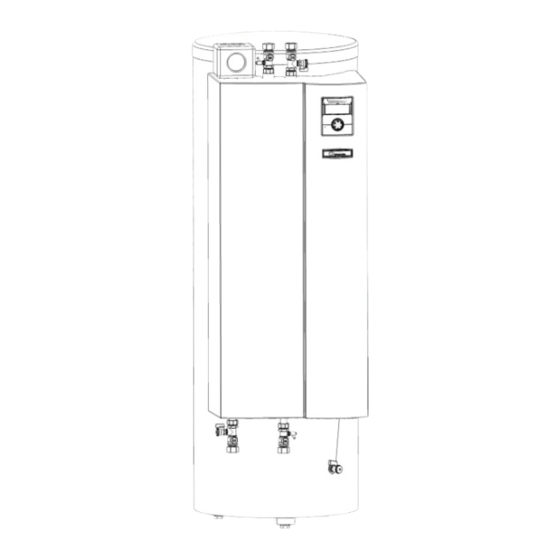
7 Shut-off ball valve with drain cock 8 Shut-off ball valve with filling and drain cock 9 Circulating pump, heating circuit (HUP) 10 Domestic hot water tank 11 Overflow valve 12 Instantaneous water heater behind heat shield 13 Changeover valve, domestic hot water 14 Heating circuit safety assembly (insulated) 15 Galvanic anode Installation / Hydraulic connection... -
Page 10: Hydraulic Connection Of Hot Water Tank
Hydraulic connection of hot water IMPORTANT tank The power supply for the heat pump and the electric heating element must be equipped Connect hot water tank according to DIN 1988 and with an all-pole automatic circuit-breaker with DIN 4753, Part 1 (or the local relevant standards, at least 3mm contact spacing to IEC 60947-2. -
Page 11: Connect Bus Cable
Connect BUS cable Strip the BUS cable insulation and push the shield back over the insulation. Insert the end of the insulated cable with the shield into the shield terminal. Feed the end with the individual cores through one of the two grommets. 1 Strain relief devices 2 Electrical switch cabinet 3 Comfort board... -
Page 12: Flushing, Filling And Venting The System
Flushing, filling and venting NOTE To ensure a good seat of the motor on the the system valve, make sure that the U-clip with the waist is not pushed past the lug, because then the motor will not be held securely on the valve! IMPORTANT In order to be supported securely, the U-clip must bear The system must be absolutely free from air... -
Page 13: Flushing, Filling And Venting The Domestic Hot Water Tank
Set the overflow valve Flushing, filling and venting the domestic hot water tank REMARQUE The activities in this section are only neces- IMPORTANT sary for in-line tank integration. Before flushing and filling the hot water tank, Complete the worksteps quickly, otherwise the drain pipe of the safety valve must be the maximum return temperature can be ex- connected. -
Page 14: Installation Of The Control Unit
Installation of the control unit At the rear of the control unit there are 4 hooks, on which the control unit panel is hung: Remove the cover at the front of the Dual hydrau- lic tower: Press down the hung control unit, until it latches into place. -
Page 15: Commissioning
Commissioning Dismantling Follow the instructions in the section entitled DANGER “Commissioning” in the operating manual for your Risk of fatal electric shock! heat pump. Electrical connections may be installed Ensure that only by qualified electricians. Before opening the unit, disconnect the ●... -
Page 16: Technical Data / Scope Of Delivery
Technical data / scope of delivery Unit designation Accessory for heat pump model LWD 50A - LWD 90A • applicable ı — not applicable • Functionally relevant • applicable ı — not applicable • Installation location Indoors ı Outdoors • applicable ı — not applicable •... -
Page 17: Performance Curves
Free compression ∆pmax “ ” (m 812032 Legende: “ ” Volumenstrom Heizwasser in m ∆pmax freie Pressung maximal (Werkseinstellung) Keys: UK812022 Flow rate heating water “” ∆pmax maximum free pressure Bezeichnung: Änd./ÄM/Ersteller/Datum Freie Pressung HTD(S) Seite: 1/1 - /PEP 015-2011 / Liska / 21.06.2012 812032 Zeichnungsnummer: D t i 812032 F i P... -
Page 18: Dimensioned Drawings
Dimensioned drawings <1800 1651 1547 1163 97 180 Keys: UK819417 All dimensions in mm. Front view Side view from left Rear view Pos. Designation Dim. Safety assembly Heating water inflow (from heating circuit) Rp 1" IG Heating water outlet (in the heating circuit) Rp 1"... -
Page 19: Installation Plan
Installation plan >1200 >100 >500 Legende: 819418 - Keys: UK819418 Technische Änderungen vorbehalten. All dimensions in mm. Alle Maße in mm. Pos. Designation OKF Oberkante Fertigfussboden Free space for service purposes Freiraum für Servicezwecke Top edge of finished floor Zust. Subject to change without notice | 83053800eUK –... -
Page 20: Hydraulic Integration Htd / Lwd
Hydraulic integration HTD / LWD Subject to change without notice | 83053800eUK – Translation of the original operating manual | ait-deutschland GmbH... -
Page 21: Legend Hydraulic Integration
Subject to change without notice | 83053800eUK – Translation of the original operating manual | ait-deutschland GmbH... -
Page 22: Terminal Diagram
Terminal diagram 3~N/PE/400V/50Hz 3~N/PE/400V/50Hz 3~N/PE/400V/50Hz ZW2/SST 1~N/PE/230V/50Hz Subject to change without notice | 83053800eUK – Translation of the original operating manual | ait-deutschland GmbH... -
Page 23: Circuit Diagrams
Circuit diagram 1/2 Subject to change without notice | 83053800eUK – Translation of the original operating manual | ait-deutschland GmbH... - Page 24 Circuit diagram 2/2 Subject to change without notice | 83053800eUK – Translation of the original operating manual | ait-deutschland GmbH...
- Page 25 Subject to change without notice | 83053800eUK – Translation of the original operating manual | ait-deutschland GmbH...
- Page 26 Subject to change without notice | 83053800eUK – Translation of the original operating manual | ait-deutschland GmbH...
-
Page 27: Ec Declaration Of Conformity
EC Declaration of Conformity The undersigned confirms that the following designated device(s) as designed and marketed by us fulfill the standardized EC directives, the EC safety standards and the product-specific EC standards. In the event of modification of the device(s) without our approval, this declaration shall become invalid. Designation of the device(s) Heat Pump Unit model... - Page 28 GmbH Industriestraße 3 D-95359 Kasendorf E info@alpha-innotec.de W www.alpha-innotec.de alpha innotec – an ait-deutschland GmbH brand...
Need help?
Do you have a question about the Dual HTD and is the answer not in the manual?
Questions and answers