IBM 8852 - BladeCenter H Rack-mountable Service Manual
Problem determination and service guide
Hide thumbs
Also See for 8852 - BladeCenter H Rack-mountable:
- Installation and user manual (82 pages)
Table of Contents
Advertisement
Advertisement
Table of Contents

Related Manuals for IBM 8852 - BladeCenter H Rack-mountable


Summary of Contents for IBM 8852 - BladeCenter H Rack-mountable
- Page 1 BladeCenter H Type 8852, 7989, and 1886 Problem Determination and Service Guide...
- Page 3 BladeCenter H Type 8852, 7989, and 1886 Problem Determination and Service Guide...
- Page 4 Before using this information and the product it supports, read: the general information in Appendix B, “Notices,” on page 63; the IBM Warranty Information document; and the IBM Safety Information and IBM Systems and Environmental Notices and User Guide documents on the IBM Documentation CD.
-
Page 5: Table Of Contents
Module LEDs. . 18 Hardware service and support . . 62 Event log messages . . 19 IBM Taiwan product service . . 62 Solving undetermined problems . 20 Calling IBM for service . 21 Appendix B. Notices ..63 Trademarks . - Page 6 Russia Electromagnetic Interference (EMI) Class Taiwan Class A compliance statement . 69 A statement . . 69 People's Republic of China Class A electronic Index ....71 emission statement .
-
Page 7: Safety
Les sikkerhetsinformasjonen (Safety Information) før du installerer dette produktet. Antes de instalar este produto, leia as Informações sobre Segurança. Antes de instalar este producto, lea la información de seguridad. Läs säkerhetsinformationen innan du installerar den här produkten. © Copyright IBM Corp. 2010... -
Page 8: Guidelines For Trained Service Technicians
Use the information in this section to help you identify potential unsafe conditions in an IBM product that you are working on. Each IBM product, as it was designed and manufactured, has required safety items to protect users and service technicians from injury. -
Page 9: Safety Statements
v Do not touch the reflective surface of a dental mirror to a live electrical circuit. The surface is conductive and can cause personal injury or equipment damage if it touches a live electrical circuit. v Some rubber floor mats contain small conductive fibers to decrease electrostatic discharge. - Page 10 DANGER Electrical current from power, telephone, and communication cables is hazardous. To avoid a shock hazard: v Do not connect or disconnect any cables or perform installation, maintenance, or reconfiguration of this product during an electrical storm. v Connect all power cords to a properly wired and grounded electrical outlet. v Connect to properly wired outlets any equipment that will be attached to this product.
- Page 11 Statement 2: CAUTION: When replacing the lithium battery, use only IBM Part Number 33F8354 or an equivalent type battery recommended by the manufacturer. If your system has a module containing a lithium battery, replace it only with the same module type made by the same manufacturer.
- Page 12 Statement 4: ≥ 18 kg (39.7 lb) ≥ 32 kg (70.5 lb) ≥ 55 kg (121.2 lb) CAUTION: Use safe practices when lifting. Statement 5: CAUTION: The power control button on the device and the power switch on the power supply do not turn off the electrical current supplied to the device.
- Page 13 Statement 8: CAUTION: Never remove the cover on a power supply or any part that has the following label attached. Hazardous voltage, current, and energy levels are present inside any component that has this label attached. There are no serviceable parts inside these components.
- Page 14 Statement 20: CAUTION: To avoid personal injury, before lifting the unit, remove all the blades to reduce the weight. (4X) (14X) (2X) 164 kg 44 kg (360 lbs) (96 lbs) Statement 21: CAUTION: Hazardous energy is present when the blade is connected to the power source. Always replace the blade cover before installing the blade.
-
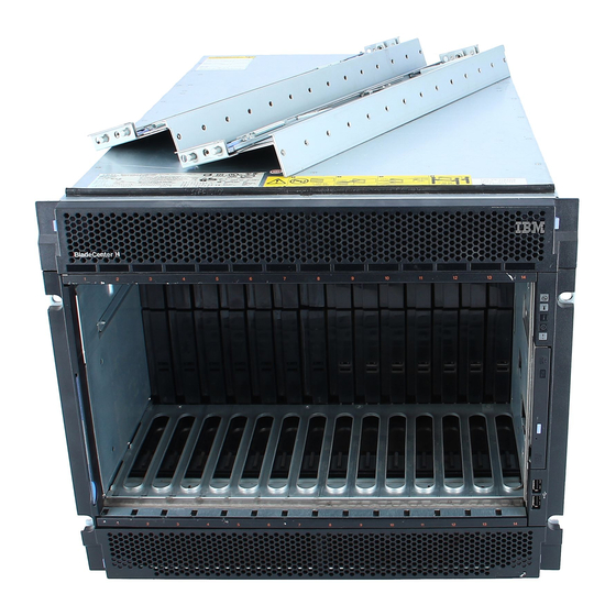
Page 15: Chapter 1. Introduction
Replaceable components are of three types: v Tier 1 customer replaceable unit (CRU): Replacement of Tier 1 CRUs is your responsibility. If IBM installs a Tier 1 CRU at your request, you will be charged for the installation. v Tier 2 customer replaceable unit: You can install a Tier 2 CRU yourself or request IBM to install it, at no additional charge, under the type of warranty service that is designated for your computer. - Page 16 BladeCenter unit documentation. These updates are available from the IBM Web site. To check for updated documentation and technical updates, go to http://www.ibm.com/support/.
-
Page 17: Notices And Statements In This Document
Notices and statements in this document The caution and danger statements that appear in this document are also in the multilingual Safety Information document, which is on the IBM Documentation CD. Each statement is numbered for reference to the corresponding statement in the Safety Information document. -
Page 18: Features And Specifications
Features and specifications The following table provides a summary of the features and specifications of the BladeCenter unit. Depending on the model, some features might not be available, or some specifications might not apply. Media tray (on front): Upgradeable microcode: Environment: v Optical drive (optional) v Management-module firmware... -
Page 19: Controls, Leds, And Connectors
Controls, LEDs, and connectors This section identifies the components, controls, and LEDs on the front and rear of the BladeCenter unit. Note: The illustrations in this document might differ from your hardware. Front view This section identifies the components, controls, and LEDs on the front of the BladeCenter unit. - Page 20 v AC power LED: When this green LED is lit, ac input to the power module is present and within specifications. During typical operation, both the ac power and dc power LEDs are lit. v Power module error LED: When this amber LED is lit, a power module has failed and is not operating within specifications.
-
Page 21: Rear View
– System-error: When this amber LED is lit, it indicates that a system error has occurred, such as a failed module or a system error in a blade server. An LED on one of the components or on a blade server is also lit to further isolate the error. - Page 22 Management modules See the documentation that comes with each management module for a description of the LEDs and connectors on the module. Blower modules When the amber LED on a blower module is lit, an error has been detected in the blower or ac power to the blower is not present.
-
Page 23: Supplying Power To The Bladecenter Unit
Supplying power to the BladeCenter unit To supply power to the BladeCenter unit, connect one end of each power cord to a power connector on the rear of the BladeCenter unit and the other end of each power cord to a 220-volt PDU that is connected to an appropriate electrical outlet. The BladeCenter unit does not have a power switch. - Page 24 BladeCenter H Type 8852, 7989, and 1886: Problem Determination and Service Guide...
-
Page 25: Chapter 2. Diagnostics
If problems or changes in status are found, the management module generates messages and displays them in the event log (see “Event log messages” on page 19). © Copyright IBM Corp. 2010... -
Page 26: Troubleshooting Tables
Troubleshooting tables Use the troubleshooting tables to find solutions to problems that have identifiable symptoms. If one or more LEDs on the BladeCenter unit or the components is lit, see “Light path diagnostic LEDs” on page 17. If you cannot find the problem in these tables, see “Solving undetermined problems”... -
Page 27: Fan Pack Problems
v Follow the suggested actions in the order in which they are listed in the Action column until the problem is solved. v See Chapter 3, “Parts listing,” on page 23 to determine which components are CRUs and which components are FRUs. -
Page 28: Keyboard, Mouse, Or Pointing-Device Problems
Keyboard, mouse, or pointing-device problems Note: These symptoms apply only to the devices that are connected to the management module; they do not apply to the remote console. v Follow the suggested actions in the order in which they are listed in the Action column until the problem is solved. -
Page 29: Media Tray Problems
v Follow the suggested actions in the order in which they are listed in the Action column until the problem is solved. v See Chapter 3, “Parts listing,” on page 23 to determine which components are CRUs and which components are FRUs. -
Page 30: Monitor Or Video Problems
Note: These symptoms apply only to the monitor that is connected to the management module; they do not apply to the remote console. Some IBM monitors have their own self-tests. If you suspect a problem with your monitor, see the documentation that comes with the monitor for instructions for testing and adjusting the monitor. -
Page 31: Light Path Diagnostic Leds
Light path diagnostic LEDs Light path diagnostic LEDs are a system of LEDs on the BladeCenter unit and the BladeCenter components that can be used to identify system errors. If the front or rear system-error LED of the BladeCenter unit is lit, one or more error LEDs on the BladeCenter components also might be lit. -
Page 32: Module Leds
Module LEDs Use the following table to find solutions to problems that are identified by LEDs on the modules installed in BladeCenter unit. Note: To find descriptions and actions for LEDs on I/O modules or blade servers, see the documentation that comes with the device. v Follow the suggested actions in the order in which they are listed in the Action column until the problem is solved. -
Page 33: Event Log Messages
Event log messages Messages that are generated while the management module is monitoring the BladeCenter unit or by the BIST program during startup are displayed in the management module event log. Each message includes a severity level (error [E], warning [W], or information [I]), a source (such as, management module [SERVPROC] or blade server number [BLADE_xx]), a timestamp, and a text description. -
Page 34: Solving Undetermined Problems
Solving undetermined problems If the diagnostic aids did not diagnose the failure or if the BladeCenter unit is inoperative, use the information in this section. Note: When you are diagnosing a problem in the BladeCenter unit, you must determine if the problem is in the BladeCenter unit, one of the BladeCenter modules, or in a blade server. -
Page 35: Calling Ibm For Service
Calling IBM for service See Appendix A, “Getting help and technical assistance,” on page 61 for information about calling IBM for service. When you call for service, have as much of the following information available as possible: v Machine type and model... - Page 36 BladeCenter H Type 8852, 7989, and 1886: Problem Determination and Service Guide...
-
Page 37: Chapter 3. Parts Listing
Replaceable components are of three types: v Tier 1 customer replaceable unit (CRU): Replacement of Tier 1 CRUs is your responsibility. If IBM installs a Tier 1 CRU at your request, you will be charged for the installation. v Tier 2 customer replaceable unit: You may install a Tier 2 CRU yourself or request IBM to install it, at no additional charge, under the type of warranty service that is designated for your server. -
Page 38: Front View
Front view CRU part CRU part number number FRU part Index Description (Tier 1) (Tier 2) number Chassis shell, without shuttle (all models) 31R3308 Bezels, top and bottom (all models) 31R3300 Power Module, 2900W, without fan pack 39Y7364 Power Module, 2980W high efficiency, with fan pack 39Y7415 Filler, power module (all models) 31R3304... - Page 39 CRU part CRU part number number FRU part Index Description (Tier 1) (Tier 2) number Ultrabay Slim CD-RW/DVD-ROM combo drive 42C0969 DVD drive, SATA, multi-burner (model 4Sx) (option) 44W3254 UltraSlim enhanced SATA multi-burner 44W3256 Media tray (supports 9.5 mm optical drives, use with midplane 31R3305 FRU 25R5780) Media tray (supports 12.7 mm optical drives, use with midplane...
-
Page 40: Rear View
Rear view CRU part CRU part number number FRU part Index Description (Tier 1) (Tier 2) number Chassis shell (without shuttle) 31R3308 Midplane (older models, chassis hardware version v6 or earlier) 25R5780 Midplane (newer models, chassis hardware version v8 or later) 44X2302 Shuttle, with card and cable assembly (all models) 31R3331... - Page 41 See the Advanced Management Module User's Guide or the Advanced Management Module Command-Line Interface Reference Guide for more information about viewing BladeCenter hardware data. ® For a list of supported options for the BladeCenter, see the ServerProven list at http://www.ibm.com/servers/eserver/serverproven/compat/us/. Chapter 3. Parts listing...
-
Page 42: Power Cords
Power cords FRU part number Description Used in these countries 26R0001 Cable, IEC 320 C20 Worldwide 26R0003 Cable, NEMA L6-30P Canada, Japan, Mexico, United States of America 26R0009 Cable, 30A 1-phase Korea 39M5436 Cable, IEC 309 32A/IEC 320 C20 Worldwide except: Australia, Canada, Japan, Korea, Mexico, New Zealand, United States of America 39M5438... -
Page 43: Chapter 4. Removing And Replacing Bladecenter Components
Replaceable components are of three types: v Tier 1 customer replaceable unit (CRU): Replacement of Tier 1 CRUs is your responsibility. If IBM installs a Tier 1 CRU at your request, you will be charged for the installation. v Tier 2 customer replaceable unit: You can install a Tier 2 CRU yourself or request IBM to install it, at no additional charge, under the type of warranty service that is designed for your computer. -
Page 44: System Reliability Guidelines
BladeCenter unit, open or close a latch, and so on. v For a list of supported options for the BladeCenter unit, see http://www.ibm.com/servers/eserver/serverproven/compat/us/. System reliability guidelines To help ensure proper system cooling and system reliability, make sure that the... -
Page 45: Removing And Replacing Tier 1 Crus
Removing and replacing Tier 1 CRUs Replacement of Tier 1 CRUs is your responsibility. If IBM installs a Tier 1 CRU at your request, you will be charged for the installation. The illustrations in this document might differ from your hardware. -
Page 46: Installing A Bezel
Installing a bezel To install either the top or bottom bezel, complete the following steps. Release buttons Release buttons 1. Align the blue tabs on the ends of the bezel with the corresponding holes in the front of the BladeCenter unit. 2. -
Page 47: Removing And Replacing The Media Tray And Optical Drive Or Optical Drive Filler
Removing and replacing the media tray and optical drive or optical drive filler Your BladeCenter is equipped with one of two different media tray FRUs, depending on the midplane connector design. Before you replace a media tray FRU, identify the part number of the media tray you are replacing either by reading the FRU label on the media tray or by logging on to the Advanced Management Module and checking Hardware VPD information for the Media Module. - Page 48 5. Press the optical drive retainer tab and slide the optical drive or optical drive filler out of the media tray. 6. Remove the retainer clip from the side of the optical drive or optical drive filler. 7. If you are instructed to return the media tray, optical drive, or optical drive filler, follow all packaging instructions, and use any packaging materials for shipping that are supplied to you.
-
Page 49: Removing And Replacing A Power Module
Removing and replacing a power module Your BladeCenter might be equipped with 2900W power modules that have a removable fan pack (part number 39Y7408), or it might be equipped with 2980W high-efficiency power modules with integrated fan pack (part number 39Y7415). The 2900W and 2980W high-efficiency power modules are not interchangeable within the same power domain of the chassis. - Page 50 Removing a power module Attention: v To help ensure proper cooling and system reliability, make sure that you replace a removed power module or filler with a power module or filler within 1 minute. v If you are removing a functioning power module, make sure that power LEDs on the remaining power modules are lit;...
- Page 51 Note: These instructions assume that the BladeCenter unit is connected to power. 1. Read the safety information that begins on page v and “Installation guidelines” on page 29. 2. Remove the top or bottom bezel as needed to access the power module to be removed (see “Removing a bezel”...
- Page 52 Note: The 2980W high-efficiency power module comes with an integrated fan pack. 2. Make sure that the handle on the power module is in the open position. 3. Orient the new power module to the selected power-module bay: v For the upper power-module bays, the rear connector on the power module must be facing down.
-
Page 53: Removing And Replacing A Fan Pack
Removing and replacing a fan pack The procedures in this section apply only to BladeCenter units equipped with 2900W power modules that have a removable fan pack (part number 39Y7408). If your BladeCenter is equipped with 2980W high-efficiency power modules with integrated fan pack (part number 39Y7415), you must replace the entire power module if the fan pack fails. - Page 54 Installing a fan pack To install a fan pack on a 2900W power module, complete the following steps. Handle Release tabs 1. Make sure that the handle is rotated down so that it is parallel with the bottom of the module, with the power module rear connector facing up. 2.
-
Page 55: Removing A Blade Server
Removing a blade server Attention: v To maintain proper system cooling, do not operate the BladeCenter unit without a blade server, expansion unit, or blade server filler installed in each blade bay. v Note the bay number. Reinstalling a blade server into a different bay from the one from which it was removed could have unintended consequences. -
Page 56: Installing A Blade Server
Installing a blade server Statement 21: CAUTION: Hazardous energy is present when the blade is connected to the power source. Always replace the blade cover before installing the blade. Attention: v Reinstalling a blade server into a different bay from the one from which it was removed could have unintended consequences. - Page 57 6. Make sure that the blade server is receiving power. See the documentation that comes with the blade server for more instructions. 7. (Optional) Write identifying information on one of the labels that come with the blade server; then, place the label on the BladeCenter unit top bezel, just above the blade server.
-
Page 58: Removing An I/O Module
Removing an I/O module To remove an I/O module or module filler, complete the following steps. Double module Single filler module filler I/O module Release handles (open) module Module Release handle filler (open) Note: These instructions assume that the BladeCenter unit is connected to power. 1. -
Page 59: Installing An I/O Module
Installing an I/O module The BladeCenter unit has 10 hot-swap I/O module bays that are compatible with three types of I/O modules (see “Rear view” on page 7 for the location of the I/O module bays). See the Installation and User’s Guide for a description of the types of modules that can be used in each bay. -
Page 60: Removing A Management Module
Removing a management module To remove a management module or filler, complete the following steps. Notes: 1. These instructions assume that the BladeCenter unit is connected to power. 2. If you are replacing the only management module in the BladeCenter unit and the management module is functioning, save the configuration file before you proceed. -
Page 61: Installing A Management Module
Installing a management module To install a management module, complete the following steps. Module filler Release handle Management (open) module Note: These instructions assume that the BladeCenter unit is connected to power. 1. Make sure that the release handle on the module is in the open position. 2. -
Page 62: Removing And Replacing A Blower Module
Removing and replacing a blower module Your BladeCenter might be equipped with standard blower modules (part number 44E5083), or it might be equipped with high-efficiency blower modules (part number 68Y8205). The standard and high-efficiency blower modules are not interchangeable and should not be mixed in the same BladeCenter unit. Attention: Failed blower modules should only be replaced with the same type of blower module. - Page 63 Installing a blower module To install a blower module, complete the following steps. Handle (open) Release button Note: These instructions assume that the BladeCenter unit is connected to power. 1. Make sure that the handle on the blower module is in the open position. 2.
-
Page 64: Removing And Replacing Frus
Removing and replacing FRUs FRUs must be installed only by trained service technicians. The illustrations in this document might differ from your hardware. Removing the shuttle To remove the shuttle, complete the following steps. Shuttle Shipping screws Release latch Captive thumb Release handle screws (open) - Page 65 7. Remove the upper and lower shipping brackets from the rear of the BladeCenter unit and the rack, if they are installed (see the Rack Installation Instructions for more information). 8. Remove the top and bottom bezels (see “Removing a bezel” on page 31). 9.
-
Page 66: Installing The Shuttle
Installing the shuttle To install the shuttle, complete the following steps. Shuttle Shipping screws Release latch Captive thumb Release handle screws (open) 1. If you are installing a new shuttle, install the midplane from the removed shuttle (see “Installing the midplane” on page 57). 2. - Page 67 9. Push the following components fully into the front of the BladeCenter unit to re-engage the midplane using the procedure indicated: v Blade servers: Push each blade server into the bay; then, push the two release handles to the closed position (see “Installing a blade server” on page 42).
-
Page 68: Removing The Rear Led/Serial Connector Assembly
Removing the rear LED/serial connector assembly To remove the rear LED/serial connector assembly, complete the following steps. 1. Read the safety information that begins on page v and “Installation guidelines” on page 29. 2. Shut down the operating systems and turn off any blade servers in the BladeCenter unit. -
Page 69: Installing The Rear Led/Serial Connector Assembly
Installing the rear LED/serial connector assembly To install the rear LED/serial connector assembly, complete the following steps. 1. Insert the assembly into the opening in the shuttle bottom; then, carefully slide it forward until the serial port is seated firmly in the opening on the back panel of the shuttle. - Page 70 2. If your BladeCenter H chassis hardware is version v8 or later, install midplane FRU 44X2302. There is no BladeCenter H chassis hardware version v7. Attention: The different midplane FRUs are not interchangeable. A failed midplane FRU should only be replaced with a midplane having the same FRU part number.
- Page 71 Attention: Note the position of the midplane between the locating tabs on each end of the lower ac cable bracket. The replacement midplane must be positioned correctly between the tabs to avoid damaging the midplane. 10. Pull the bottom of the midplane away from the shuttle; then, lift the midplane out of the tabs in the lower ac cable bracket.
- Page 72 8. Install the shuttle into the BladeCenter unit (see “Installing the shuttle” on page 52). 9. Reconnect the power to the BladeCenter unit (see “Supplying power to the BladeCenter unit” on page 9). 10. Restart any blade servers that were shut down in the BladeCenter unit. See the documentation that comes with the blade server for detailed instructions.
-
Page 73: Chapter 5. Configuration Information And Guidelines
The firmware for the management module and other BladeCenter components is periodically updated and is available for download on the Web. Go to http://www.ibm.com/support/ to get the latest level of firmware, such as BIOS code and device drivers. Note: When replacing BladeCenter components, you might have to update the management module or other components with the latest version of firmware. -
Page 74: Configuring Blade Servers
Configuring blade servers To achieve communication redundancy on a blade server, you must configure the Ethernet controllers on the blade servers for failover. When failover occurs on a blade server, the secondary Ethernet controller takes over network communications, using the I/O module that is associated with that controller. Install a pair of Ethernet switches in I/O-module bays 1 and 2;... -
Page 75: Appendix A. Getting Help And Technical Assistance
If you need help, service, or technical assistance or just want more information about IBM products, you will find a wide variety of sources available from IBM to assist you. This section contains information about where to go for additional information about IBM and IBM products, what to do if you experience a problem with your system, and whom to call for service, if it is necessary. -
Page 76: Getting Help And Information From The World Wide Web
Getting help and information from the World Wide Web On the World Wide Web, the IBM Web site has up-to-date information about IBM ® systems, optional devices, services, and support. The address for IBM System x ® and xSeries information is http://www.ibm.com/systems/x/. The address for IBM BladeCenter information is http://www.ibm.com/systems/bladecenter/. -
Page 77: Appendix B. Notices
Consult your local IBM representative for information on the products and services currently available in your area. Any reference to an IBM product, program, or service is not intended to state or imply that only that IBM product, program, or service may be used. Any functionally equivalent product, program, or service that does not infringe any IBM intellectual property right may be used instead. -
Page 78: Important Notes
A current list of IBM trademarks is available on the Web at “Copyright and trademark information” at http://www.ibm.com/ legal/copytrade.shtml. Adobe and PostScript are either registered trademarks or trademarks of Adobe Systems Incorporated in the United States and/or other countries. -
Page 79: Particulate Contamination
IBM makes no representations or warranties with respect to non-IBM products. Support (if any) for the non-IBM products is provided by the third party, not IBM. Some software might differ from its retail version (if available) and might not include user manuals or all program functionality. -
Page 80: Electronic Emission Notices
In the request, be sure to include the publication part number and title. When you send information to IBM, you grant IBM a nonexclusive right to use or distribute the information in any way it believes appropriate without incurring any obligation to you. -
Page 81: Germany Class A Statement
Klasse A ein. Um dieses sicherzustellen, sind die Geräte wie in den Handbüchern beschrieben zu installieren und zu betreiben. Des Weiteren dürfen auch nur von der IBM empfohlene Kabel angeschlossen werden. IBM übernimmt keine Verantwortung für die Einhaltung der Schutzanforderungen, wenn das Produkt ohne Zustimmung der IBM verändert bzw. -
Page 82: Japan Vcci Class A Statement
914-499-1900 Der verantwortliche Ansprechpartner des Herstellers in der EU ist: IBM Deutschland Technical Regulations, Department M456 IBM-Allee 1, 71137 Ehningen, Germany Telephone: +49 7032 15-2937 E-mail: tjahn@de.ibm.com Generelle Informationen: Das Gerät erfüllt die Schutzanforderungen nach EN 55024 und EN 55022 Klasse... -
Page 83: A Statement
Russia Electromagnetic Interference (EMI) Class A statement People's Republic of China Class A electronic emission statement Taiwan Class A compliance statement Appendix B. Notices... - Page 84 BladeCenter H Type 8852, 7989, and 1886: Problem Determination and Service Guide...
- Page 85 57 power module 37 eject button rear LED/serial connector CD 7 assembly 55 electrical input 4 online publications 2 shuttle 52 electronic emission Class A notice 66 Optical drive environment 4 activity LED 7 © Copyright IBM Corp. 2010...
- Page 86 Optical drive (continued) removing and replacing eject button 7 media tray 33 problems 15 Optical drive 33 removing and replacing 33 Optical drive filler 33 Optical drive filler Removing and replacing removing and replacing 33 fan pack 39 over-temp LED 6 midplane 55 power module 35 replacement parts...
- Page 88 Part Number: 81Y1107 Printed in USA (1P) P/N: 81Y1107...
Need help?
Do you have a question about the 8852 - BladeCenter H Rack-mountable and is the answer not in the manual?
Questions and answers