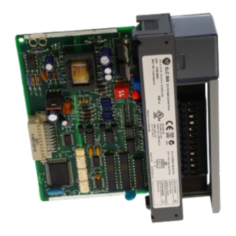
Summarization of Contents
Preface
Who Should Use this Manual
Identifies the target audience responsible for SLC 500 analog I/O systems.
Purpose of this Manual
Outlines the manual's scope: installation, wiring, and troubleshooting.
Related Documentation
Document References
Lists other documents for additional information on Rockwell Automation products.
Manual Conventions
Common Techniques Used
Explains conventions used throughout the manual for clarity.
Feedback and Support
Provides contact information for manual feedback and support.
Chapter 1 Overview
How to Use Analog
Explains analog representation and a typical application example.
Types of Analog Modules
Provides an overview of the different analog modules available.
Chapter 2 Quick Start for Experienced Users
Required Tools and Equipment
Lists necessary tools and equipment for quick installation.
Quick Start Procedures
Outlines the step-by-step procedures for quick start.
Chapter 3 Installing and Wiring Your Analog Module
Regulatory Compliance
Specifies regulations applicable within the EU or EEA regions and EMC standards.
Power Requirements
Guides on calculating power requirements for modular and fixed controllers.
Module Configuration
Explains setting up analog input channels using DIP switches.
External Power Switch
Describes the external power switch for output modules.
Installation Procedures
Covers slot selection, physical installation, and terminal block handling.
Wiring Considerations
Details system wiring guidelines, grounding, and cable length.
Wiring Procedures and Schematics
Step-by-step wiring, terminal block handling, and noise reduction techniques.
Chapter 4 Module Operation and System Considerations
Module-Processor Interface
Describes module setup, ID codes, and interface with the SLC 500 system.
Addressing Analog Modules
Details how analog modules and their channels are addressed in the I/O image table.
Bit Level Addressing
Illustrates bit maps for analog inputs and outputs for detailed addressing.
Data Processing and Monitoring
Explains processor data updates, monitoring, and signal conversion methods.
System Considerations
Covers safe states, retentive programming, out-of-range detection, slot disable, and filtering.
Chapter 5 Testing Your Module
System and Module Testing
Guides on testing the SLC 500 system and analog module start-up procedures.
Analog Input Testing
Detailed procedure for testing the analog module input channels.
Analog Output Testing
Detailed procedure for testing the analog module output channels.
Chapter 6 Programming Examples
Analog Input Programming Examples
Examples for addressing, range checking, and scaling analog inputs using various methods.
Analog Output Programming Examples
Examples for addressing, scaling, and handling offsets for analog outputs.
Scaling and Range Checking Examples
Demonstrates scaling and range checking for both analog inputs and outputs.
Chapter 7 Maintenance and Safety
Preventative Maintenance
Information on maintaining analog modules and SLC 500 systems.
Safety Considerations
Highlights safety precautions for troubleshooting system issues.
Appendix A Specifications
General Specifications
Lists general technical specifications for the analog modules.
Input Specifications
Details current and voltage input specifications for the analog modules.
Output Specifications
Details current and voltage output specifications for the analog modules.
Appendix B Two’s Complement Binary Numbers
Positive Decimal Values
Explains how positive numbers are represented in two's complement binary format.
Negative Decimal Values
Explains how negative numbers are represented in two's complement binary format.
Appendix C Optional Analog Input Software Calibration
Software Calibration Procedure
Steps, equations, and examples for calibrating analog input channels via software.
Appendix D Module Input and Output Circuits
Input Circuit Schematics
Shows internal input circuit schematics for NI4, NIO4I, and NIO4V modules.
Output Circuit Schematics
Shows internal voltage and current output circuit schematics for relevant modules.
Rockwell Automation Support
Installation Assistance
Offers initial support for hardware module installation issues.
Product Return Process
Outlines the process for returning non-functioning products for satisfaction.


Need help?
Do you have a question about the 1746-NO4I and is the answer not in the manual?
Questions and answers