Table of Contents
Advertisement
Quick Links
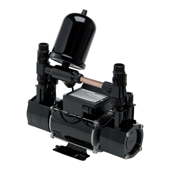
SHOWERMATE
Installation, Operation & Maintenance
Instructions
Please leave this instruction booklet with the home owner as it contains
important guarantee, maintenance and safety information
Read this manual carefully before commencing installation.
This manual covers the following products:
Showermate U2.6 bar Single
Pt. No. 46534
FOR POSITIVE OR NEGATIVE HEAD APPLICATIONS
Pt. No. 46534 EXP
Showermate U1.8 bar Twin
Pt. No. 46532
Showermate U2.6 bar Twin
Pt. No. 46533
Pt. No. 46533 EXP
3
CE compliant product
Advertisement
Table of Contents

Related Manuals for Stuart Turner SHOWERMATE 46533 EXP


Summarization of Contents
CHECKLIST
PRE-INSTALLATION CHECK
Verifies all pump components are present and undamaged before installation begins.
IMPORTANT FACTS: READ BEFORE COMMENCING PUMP INSTALLATION
Water storage capacity
Ensures sufficient water storage capacity to meet required flow rates for pumped equipment and appliances.
Water temperature
Specifies maximum (65°C) and minimum (4°C) water temperatures for pump operation.
Pipework – General
Guidelines for secure pipework, flux usage, pipework design, and avoiding contamination.
Plumbing Installation Regulations
Requirements for plumbing installations to comply with current water and building regulations.
Pressure vessel
Information on the pressure vessel's factory charge and maintenance details.
LOCATION – GENERAL
Access
Ensures the pump is easily accessible for emergencies and maintenance operations.
Protection
Recommends locating the pump in a dry, frost-free, and protected position to prevent damage.
Ventilation
Advises maintaining adequate airflow around the pump for cooling purposes.
Safety
Warns that the motor casing can get hot and requires care to prevent touching during operation.
Water retention
Sites the pump where leaks are contained or routed to avoid water damage to sensitive areas.
Static inlet pressure
Checks static inlet head requirements (0.5m min, 6m max) before selecting the pump location.
Ambient temperature
Specifies the maximum ambient temperature for pump siting at 40°C.
Pipework
Recommends 22mm pipework for optimum performance, reducing to 15mm at terminal fittings.
Static outlet pressure
Ensures the static outlet head is within the maximum requirements for proper operation.
Noise
Suggests using anti-vibration feet and flexible hoses to reduce noise transmission.
Direction of flow
Confirms water flow direction is aligned with the arrow on the flow switch reed clamp.
Flexible hoses
Mandates the use of Stuart Turner supplied hose sets for pump connections.
Isolating valves
Requires fitting non-restrictive isolating valves for easy pump servicing.
Strainers
Advises fitting strainers to prevent pump damage from water supply debris.
Preferred pump location
Recommends siting the pump close to the hot water cylinder, below its take-off.
LOCATION – SINGLE PUMP
Non-preferred pump location
Addresses risks of introducing air when positioning the pump above the hot cylinder tapping.
LOCATION – TWIN PUMP
Cold water connection
Specifies a dedicated, air-free cold water supply connection for the pump.
Hot water connection
Hot water cylinder or storage tank
Ensures adequate pipework size (min 22mm) from cold to hot water storage.
Hot water supply
The pump must be supplied with a dedicated, air-free feed from the hot water cylinder.
Expansion pipe
Details requirements for connections made via the expansion pipe, including tank height.
PUMP CONNECTIONS
Pumps supplied with flexible inlet and outlet hoses
Connects pump ports using G 3/4 male fittings with appropriate sealing washers for watertight seals.
Hose to pump
Guides connecting flexible hoses to pump ports using G 3/4 female running nuts, nipped with pliers.
Hose to pipework
Instructions for connecting hoses to pipework using push-in connectors with specific pipe types.
Typical Low Level Installation
Options for installing 90° bends on pump connections for low-level installations.
ELECTRICAL INSTALLATION
Regulations
Electrical installation must comply with national regulations and be done by a qualified person.
Safety
Use of a 30 mA residual current device (RCD) is recommended for electrical safety.
Wiring Of Connection Unit
Correctly connects mains lead wires (Green/Yellow, Blue, Brown) to terminals E, N, L.
Wiring Diagrams
Provides diagrams illustrating single and twin pump electrical connections for reference.
Fuses
Specifies a 5 Amp fuse size for all pump models as per the technical specification.
Supply Cord Replacement
Instructions on replacing the supply cord, emphasizing maintaining original routing for compliance.
Cable Gland Fitting Instructions
Details the correct assembly of the cable gland, including O-ring placement before tightening.
COMMISSIONING
System Flushing
Flushes pipework to remove contaminants before connecting the pump to prevent damage.
Water Supply
Ensures adequate water supply and pump chamber fullness to prevent dry running.
Priming
Step-by-step guide to priming the pump with water before operation to protect the seal.
Starting
Sequence for starting the pump, pressurizing the system, and purging air from outlets.
MAINTENANCE
Turn off water supplies to the pump and release pressure
Initial steps for maintenance: isolate power, water supplies, and release system pressure.
Pressure vessel
Procedure for checking and replenishing the air charge in the pressure vessel using a Schrader valve.
Water scale
Advises periodic pump operation to prevent water scale buildup on seals.
Cleaners, Disinfectants and Descalents
Warns against using aggressive cleaning agents directly on the pump; system must be flushed.
TROUBLE SHOOTING GUIDE
Pump will not start
Troubleshooting steps for pump failure to start, covering electrical supply and mechanical issues.
Reduced/intermittent flow
Solutions for low or inconsistent water flow, including pipework, filters, and temperature checks.
No hot water
Diagnosing issues when only hot water is not supplied, checking heat source and cylinder status.
Pump runs on with outlets closed
Identifying causes for continuous pump operation with closed outlets, pointing to circuit issues.
Pump cycles (hunts) on/off frequently
Addressing frequent pump cycling by checking pressure vessel and flow switch operation.
Flexible hose leaks
Identifying and rectifying leaks from flexible hoses, checking fittings and 'O'-rings.
Dry Run Protection
Explanation of the dry run protection feature and the pump's protective logic sequence.
Protective Logic Sequence
Details the pump's automatic shutdown and restart sequence when water starvation is detected.
Fault Finding
Guidance on checking the PCB's 'power on' indicator light for fault diagnosis.
Flow Switch Circuit Test
Procedure to test the flow switch circuit using a magnet to check for correct operation.
Environment Protection
Guidance on responsible disposal of the appliance at its end of useful life.
Need help?
Do you have a question about the SHOWERMATE 46533 EXP and is the answer not in the manual?
Questions and answers