
Related Manuals for Airwell DLS 24


Summary of Contents for Airwell DLS 24
- Page 1 DLS Series Indoor Units Outdoor Units GC18 DLS 18 GC18T ONG3-17 GCN 24 DLS 24 GCN 24Z GCN 24T GCN 30 DLS 30 GCN 30T GCN 37 DLS 37 GCN 37T GCN 42 DLS 44 GCN 40T REFRIGERANT COOLING ONLY...
- Page 2 LIST OF EFFECTIVE PAGES LIST OF EFFECTIVE PAGES Note: Changes in the pages are indicated by a “Revision#” in the footer of each effected page (when none indicates no changes in the relevant page). All pages in the following list represent effected/ non effected pages divided by chapters.
- Page 3 TABLE OF CONTENTS Table of Contents INTRODUCTION ....................1-1 PRODUCT DATA SHEET ..................2-1 RATING CONDITIONS ..................3-1 OUTLINE DIMENSIONS ..................4-1 PERFORMANCE DATA & PRESSURE CURVES ..........5-1 AIRFLOW CURVES ....................6-1 SOUND LEVEL CHARACTERISTICS ..............7-1 ELECTRICAL DATA ....................8-1 WIRING DIAGRAMS .....................9-1 10. ELECTRICAL CONNECTIONS ................10-1 11.
- Page 4 The new DLS ducted split unit range comprises the ST (cooling only) as well as RC (heat pump) models, it is available at 1PH, 3PH as follow: • => DLS 18, 24, 30, 37, 44 • => DLS 18, 24, 30, 37, 44 Remote control compatibility •...
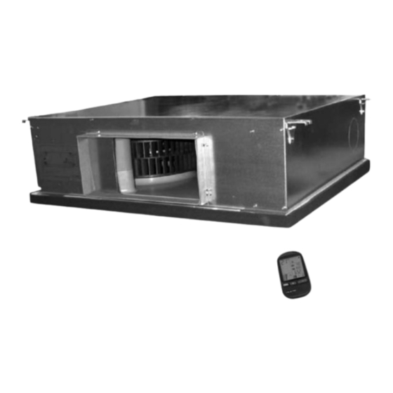
- Page 5 INTRODUCTION Indoor Unit The indoor unit can fit easily to many types of residential and commercials applications. It includes: • High technology plastic fan and fan housing. • A drain pool that is under the entire unit with internal downward slope. •...
- Page 6 Product Data Sheet, Chapter 2. It includes: • Compressor mounted in a soundproofed compartment : Rotary – for DLS 18, 24, 30, 37 Scroll – for DLS 42, 44 • Improved 3 - blades axial fans for noise reduction.
- Page 7 PRODUCT DATA SHEET PRODUCT DATA SHEET DLS 18 / GC 18 1PH R410A DLS 18 Model Indoor Unit GC 18 R410A Model Outdoor Unit DUCTED Installation Method Characteristics Units Cooling Heating Btu/hr 19100 18000 Capacity Power Input 3.05 3.12 Energy Efficiency Class...
- Page 8 PRODUCT DATA SHEET DLS 18 / GC 18T R410A DLS 18 Model Indoor Unit GC 18T R410A Model Outdoor Unit DUCTED Installation Method Characteristics Units Cooling Heating Btu/hr 19100 18000 Capacity Power Input 3.05 3.12 Energy Efficiency Class Power Supply...
- Page 9 PRODUCT DATA SHEET DLS 24 / GCN 24 1PH R410A DLS 24 Model Indoor Unit GCN 24 R410A Model Outdoor Unit DUCTED Installation Method Characteristics Units Cooling Heating Btu/hr 23500 23850 Capacity Power Input 3.04 Energy Efficiency Class Power Supply V/Ph/Hz 230/50/1 Rated Current...
- Page 10 PRODUCT DATA SHEET DLS 24 / GCN 24T R410A DLS 24 Model Indoor Unit GCN 24T R410A Model Outdoor Unit DUCTED Installation Method Characteristics Units Cooling Heating Btu/hr 23500 23850 Capacity Power Input 3.03 Energy Efficiency Class Power Supply V/Ph/Hz 400/50/3 Rated Current 3*5.4...
- Page 11 PRODUCT DATA SHEET DLS 24 / GCN 24Z 1PH R410A DLS 24 Model Indoor Unit GCN 24Z R410A Model Outdoor Unit DUCTED Installation Method Characteristics Units Cooling Heating Btu/hr 23500 23850 Capacity Power Input 3.04 Energy Efficiency Class Power Supply V/Ph/Hz 230/50/1 Rated Current...
- Page 12 PRODUCT DATA SHEET DLS 30 / GCN 30 1PH R410A DLS 30 Model Indoor Unit GCN 30 R410A Model Outdoor Unit DUCTED Installation Method Characteristics Units Cooling Heating Btu/hr 29000 30700 Capacity Power Input 2.81 3.22 Energy Efficiency Class Power Supply V/Ph/Hz 230/50/1 Rated Current...
- Page 13 PRODUCT DATA SHEET DLS 30 / GCN 30T R410A DLS 30 Model Indoor Unit GCN 30T R410A Model Outdoor Unit DUCTED Installation Method Characteristics Units Cooling Heating Btu/hr 29000 30700 Capacity Power Input 2.82 3.24 Energy Efficiency Class Power Supply V/Ph/Hz 400/50/3 Rated Current...
- Page 14 PRODUCT DATA SHEET DLS 37 / GCN 37 R410A DLS 37 Model Indoor Unit GCN 37 R410A Model Outdoor Unit DUCTED Installation Method Characteristics Units Cooling Heating Btu/hr 36350 38200 Capacity 10.6 11.2 Power Input 2.81 3.05 Energy Efficiency Class Power Supply V/Ph/Hz 230/50/1...
- Page 15 PRODUCT DATA SHEET DLS 37 / GCN 37T R410A DLS 37 Model Indoor Unit GCN 37T R410A Model Outdoor Unit DUCTED Installation Method Characteristics Units Cooling Heating Btu/hr 35480 37870 Capacity 10.4 11.1 Power Input 2.83 2.83 Energy Efficiency Class Power Supply V/Ph/Hz 400/50/3...
- Page 16 PRODUCT DATA SHEET 2.10 DLS 44 / OU10-42 1PH R410A DLS 44 Model Indoor Unit OU10-42 R410A Model Outdoor Unit DUCTED Installation Method Characteristics Units Cooling Heating Btu/hr 41630 44700 Capacity 12.20 13.10 Power Input 4.34 4.37 2.81 3.00 Energy Efficiency Class Power Supply V/Ph/Hz 230/50/1...
- Page 17 PRODUCT DATA SHEET 2.11 DLS 44 / GCN 40T R410A DLS 44 Model Indoor Unit GCN 40T R410A Model Outdoor Unit DUCTED Installation Method Characteristics Units Cooling Heating Btu/hr 43000 48450 Capacity 12.6 14.2 Power Input 4.67 4.73 Energy Efficiency Class Power Supply V/Ph/Hz 400/50/3...
- Page 18 RATING CONDITIONS RATING CONDITIONS Standard conditions in accordance with ISO 5151 and ISO 13253 (for ducted units) and EN 14511. Cooling: Indoor: C DB 19 C WB Outdoor: 35 C DB Heating: Indoor: C DB Outdoor: 7 C DB 6 C WB Operating Limits Indoor...
- Page 19 OUTLINE DIMENSIONS OUTLINE DIMENSIONS Indoor Unit: DLS 18, 24, 30, 37, 44 Model DNG 18,24,30 DNG 37,44 SM DLSRPM 1-A.4 GB CONTENTS...
- Page 20 OUTLINE DIMENSIONS Outdoor Unit: GC 18 Outdoor Unit: GCN 24, GCN 24Z SM DLSRPM 1-A.4 GB CONTENTS...
- Page 21 OUTLINE DIMENSIONS Outdoor Unit: GCN 30 Outdoor Unit: GCN 37, 42, 40T SM DLSRPM 1-A.4 GB CONTENTS...
- Page 22 PERFORMANCE DATA & PRESSURE CURVES PERFORMANCE DATA & PRESSURE CURVES DLS 18 / GC18 1PH / 3PH 5.1.1 Cooling Capacity (kW) ENTERING AIR WB/DB ID COIL ( °C) ENTERING AIR DATA DB OU COIL (°C) 15/21 17/24 19/27 21/29 23/32 5.90...
- Page 23 PERFORMANCE DATA & PRESSURE CURVES 5.1.2 Heating ENTERING AIR DB ID COIL( ENTERING WB OD COIL( 3.06 1.36 2.94 1.45 2.83 1.52 3.29 1.39 3.18 1.47 3.06 1.55 3.50 1.41 3.38 1.50 3.26 1.58 4.26 1.48 4.08 1.57 3.91 1.67 5.30 1.70 5.46...
- Page 24 PERFORMANCE DATA & PRESSURE CURVES Pressure Curves 5.3.1 Cooling Suction Pressure VS.Outdoor Temp 12.0 21/15(DB/WB ºC) 11.5 24/17(DB/WB ºC) 11.0 27/19(DB/WB ºC) 10.5 29/21(DB/WB ºC) 32/23(DB/WB ºC) 10.0 Outdoor Temp.(DB Discharge Pressure VS.Outdoor Temp 21/15(DB/WB ºC) 24/17(DB/WB ºC) 27/19(DB/WB ºC) 29/21(DB/WB ºC) 32/23(DB/WB ºC) Outdoor Temp.(DB...
- Page 25 PERFORMANCE DATA & PRESSURE CURVES 5.3.2 Heating Suction Pressure VS.Outdoor Temp' 10.0 15 DB (ºC) 20 DB (ºC) 25 DB (ºC) Outdoor Temp.( WB Discharge Pressure VS.Outdoor Temp' 25 DB (ºC) 20 DB (ºC) 15 DB (ºC) Outdoor Temp.( WB SM DLSRPM 1-A.4 GB CONTENTS...
- Page 26 PERFORMANCE DATA & PRESSURE CURVES DLS 24 / GCN 24, DLS 24 / GCN 24Z 5.4.1 Cooling Capacity (kW) ENTERING AIR WB/DB ID COIL ( °C) ENTERING AIR DATA DB OU COIL (°C) 15/21 17/24 19/27 21/29 23/32 7.27 7.53 7.71 7.89 8.01...
- Page 27 PERFORMANCE DATA & PRESSURE CURVES 5.4.2 Heating ENTERING AIR DB ID COIL( ENTERING WB OD COIL( 4.04 1.84 3.89 1.96 3.73 2.06 4.35 1.89 4.20 1.99 4.04 2.10 4.62 1.91 4.47 2.02 4.31 2.14 5.62 2.00 5.39 2.13 5.16 2.25 7.00 2.30 7.21...
- Page 28 PERFORMANCE DATA & PRESSURE CURVES Pressure Curves 5.6.1 Cooling Suction Pressure VS.Outdoor Temp 12.0 11.5 21/15(DB/WB ºC) 11.0 24/17(DB/WB ºC) 27/19(DB/WB ºC) 10.5 29/21(DB/WB ºC) 10.0 32/23(DB/WB ºC) Outdoor Temp.(DB Discharge Pressure VS.Outdoor Temp 21/15(DB/WB ºC) 24/17(DB/WB ºC) 27/19(DB/WB ºC) 29/21(DB/WB ºC) 32/23(DB/WB ºC) Outdoor Temp.(DB...
- Page 29 PERFORMANCE DATA & PRESSURE CURVES 5.6.2 Heating Suction Pressure VS.Outdoor Temp 10.0 15 DB (ºC) 20 DB (ºC) 25 DB (ºC) Outdoor Temp.( WB Discharge Pressure VS.Outdoor Temp 25 DB (ºC) 20 DB (ºC) 15 DB (ºC) Outdoor Temp.( WB SM DLSRPM 1-A.4 GB CONTENTS...
- Page 30 PERFORMANCE DATA & PRESSURE CURVES DLS 30 / GCN 30 1PH / 3PH 5.7.1 Cooling Capacity (kW) ENTERING AIR WB/DB ID COIL ( °C) ENTERING AIR DATA DB OU COIL (°C) 15/21 17/24 19/27 21/29 23/32 8.96 9.28 9.50 9.72 9.87 6.36 6.63...
- Page 31 PERFORMANCE DATA & PRESSURE CURVES 5.7.2 Heating ENTERING AIR DB ID COIL( ENTERING WB OD COIL( 5.20 2.24 5.00 2.39 4.80 2.51 5.59 2.30 5.40 2.42 5.20 2.55 5.94 2.32 5.74 2.46 5.54 2.60 6.93 2.59 7.23 2.44 6.63 2.74 9.00 2.80 9.27...
- Page 32 PERFORMANCE DATA & PRESSURE CURVES Pressure Curves 5.9.1 Cooling Suction Pressure VS.Outdoor Temp' 12.0 11.5 21/15(DB/WB ºC) 24/17(DB/WB ºC) 11.0 27/19(DB/WB ºC) 10.5 29/21(DB/WB ºC) 10.0 32/23(DB/WB ºC) Outdoor Temp.(DB Discharge Pressure VS.Outdoor Temp' 21/15(DB/WB ºC) 24/17(DB/WB ºC) 27/19(DB/WB ºC) 29/21(DB/WB ºC) 32/23(DB/WB ºC) Outdoor Temp.(DB...
- Page 33 PERFORMANCE DATA & PRESSURE CURVES 5.9.2 Heating Suction Pressure VS.Outdoor Temp' 10.0 15 DB (ºC) 20 DB (ºC) 25 DB (ºC) Outdoor Temp.( WB Discharge Pressure VS.Outdoor Temp' 25 DB (ºC) 20 DB (ºC) 15 DB (ºC) Outdoor Temp.( WB 5-12 SM DLSRPM 1-A.4 GB CONTENTS...
- Page 34 PERFORMANCE DATA & PRESSURE CURVES 5.10 DLS 37 / GCN 37 1PH 5.10.1 Cooling Capacity (kW) ENTERING AIR WB/DB ID COIL ( °C) ENTERING AIR DATA DB OU COIL (°C) 15/21 17/24 19/27 21/29 23/32 11.17 11.57 11.85 12.12 12.31 8.02 8.36 8.69...
- Page 35 PERFORMANCE DATA & PRESSURE CURVES 5.10.2 Heating ENTERING AIR DB ID COIL( ENTERING WB OD COIL( 6.47 2.94 6.22 3.13 5.98 3.28 6.96 3.01 6.71 3.17 6.47 3.35 7.39 3.05 7.15 3.23 6.90 3.41 8.62 3.39 8.99 3.19 8.25 3.60 11.20 3.67 11.54...
- Page 36 PERFORMANCE DATA & PRESSURE CURVES 5.12 DLS 37 / GCN 37 3PH 5.12.1 Cooling Capacity (kW) ENTERING AIR WB/DB ID COIL ( °C) ENTERING AIR DATA DB OU COIL (°C) 15/21 17/24 19/27 21/29 23/32 10.96 11.35 11.62 11.90 12.08 7.87 8.21 8.53...
- Page 37 PERFORMANCE DATA & PRESSURE CURVES 5.12.2 Heating ENTERING AIR DB ID COIL( ENTERING WB OD COIL( 6.41 2.86 6.17 3.05 5.92 3.20 6.90 2.94 6.65 3.10 6.41 3.26 7.33 2.97 7.08 3.15 6.84 3.33 8.55 3.31 8.91 3.11 8.18 3.51 11.10 3.58 11.43...
- Page 38 PERFORMANCE DATA & PRESSURE CURVES 5.14 Pressure Curves – DLS 37 1PH/3PH 5.14.1 Cooling Suction Pressure VS.Outdoor Temp 12.0 11.5 21/15(DB/WB ºC) 11.0 24/17(DB/WB ºC) 27/19(DB/WB ºC) 10.5 29/21(DB/WB ºC) 10.0 32/23(DB/WB ºC) Outdoor Temp.(DB Discharge Pressure VS.Outdoor Temp 21/15(DB/WB ºC) 24/17(DB/WB ºC) 27/19(DB/WB ºC) 29/21(DB/WB ºC)
- Page 39 PERFORMANCE DATA & PRESSURE CURVES 5.14.2 Heating Suction Pressure VS.Outdoor Temp 10.0 15 DB (ºC) 20 DB (ºC) 25 DB (ºC) Outdoor Temp.( WB Discharge Pressure VS.Outdoor Temp 25 DB (ºC) 20 DB (ºC) 15 DB (ºC) Outdoor Temp.( WB 5-18 SM DLSRPM 1-A.4 GB CONTENTS...
- Page 40 PERFORMANCE DATA & PRESSURE CURVES 5.15 DLS 44 / GCN 42 R410A 5.15.1 Cooling Capacity (kW) Entering Air WB/DB ID Coil( Entering Air DB Data OD Coil ( 15/21 17/24 19/27 21/29 23/32 12.86 13.32 13.63 13.96 14.17 8.70 9.07 9.42 9.66 9.84...
- Page 41 PERFORMANCE DATA & PRESSURE CURVES 5.15.2 Heating ENTERING AIR DB ID COIL( ENTERING WB OD COIL( 6.88 3.50 6.62 3.72 6.35 3.91 7.40 3.58 7.14 3.78 6.88 3.99 7.86 3.63 7.60 3.85 7.34 4.06 9.56 3.80 9.17 4.04 8.78 4.28 13.10 4.37 13.49...
- Page 42 PERFORMANCE DATA & PRESSURE CURVES 5.17 Pressure Curves 5.17.1 Cooling Suction Pressure VS.Outdoor Temp 12.0 15/21(WB/DB ºC) 11.0 17/24(WB/DB ºC) 19/27(WB/DB ºC) 21/29(WB/DB ºC) 10.0 23/32(WB/DB ºC) Outdoor Temp.(DB Discharge Pressure VS.Outdoor Temp 15/21(WB/DB ºC) 17/24(WB/DB ºC) 19/27(WB/DB ºC) 21/29(WB/DB ºC) 23/32(WB/DB ºC) Outdoor Temp.(DB SM DLSRPM 1-A.4 GB...
- Page 43 PERFORMANCE DATA & PRESSURE CURVES 5.17.2 Heating Suction Pressure VS.Outdoor Temp 10.0 15 DB (ºC) 20 DB (ºC) 25 DB (ºC) Outdoor Temp.( WB Discharge Pressure VS.Outdoor Temp 25 DB (ºC) 20 DB (ºC) 15 DB (ºC) Outdoor Temp.( WB 5-22 SM DLSRPM 1-A.4 GB CONTENTS...
- Page 44 PERFORMANCE DATA & PRESSURE CURVES 5.18 DLS 44 / GCN 40T 5.18.1 Cooling Capacity (kW) Entering Air WB/DB ID Coil( Entering Air DB Data OD Coil 15/21 17/24 19/27 21/29 23/32 13.28 13.75 14.08 14.41 14.63 9.05 9.44 9.80 10.05 10.23 3.31 3.32...
- Page 45 PERFORMANCE DATA & PRESSURE CURVES 5.18.2 Heating ENTERING AIR DB ID COIL( ENTERING WB OD COIL( 7.46 3.78 7.17 4.03 6.89 4.23 8.02 3.88 7.74 4.09 7.46 4.31 8.52 3.93 8.24 4.16 7.95 4.40 10.37 4.12 9.94 4.38 9.51 4.64 14.20 4.73 14.63...
- Page 46 PERFORMANCE DATA & PRESSURE CURVES 5.20 Pressure Curves 5.20.1 Cooling Suction Pressure VS.Outdoor Temp 12.0 11.5 15/21(WB/DB ºC) 17/24(WB/DB ºC) 11.0 19/27(WB/DB ºC) 10.5 21/29(WB/DB ºC) 23/32(WB/DB ºC) 10.0 Outdoor Temp.(DB Discharge Pressure VS.Outdoor Temp 15/21(WB/DB ºC) 17/24(WB/DB ºC) 19/27(WB/DB ºC) 21/29(WB/DB ºC) 23/32(WB/DB ºC) Outdoor Temp.(DB...
- Page 47 PERFORMANCE DATA & PRESSURE CURVES 5.20.2 Heating Suction Pressure VS.Outdoor Temp 11.0 10.0 15 DB (ºC) 20 DB (ºC) 25 DB (ºC) Outdoor Temp.( WB Discharge Pressure VS.Outdoor Temp 25 DB (ºC) 20 DB (ºC) 15 DB (ºC) Outdoor Temp.( WB 5-26 SM DLSRPM 1-A.4 GB CONTENTS...
- Page 48 AIRFLOW CURVES AIRFLOW CURVES Model: DLS 18 Low Speed Medium Speed High Speed Super Speed Operating range Model: DLS 24 Low Speed Medium Speed High Speed Super Speed Operating range SM DLSRPM 1-A.4 GB CONTENTS...
- Page 49 AIRFLOW CURVES Model: DLS 30 Low Speed Medium Speed High Speed Super Speed Operating range Model: DLS 37 Low Speed Medium Speed High Speed Super Speed Operating range SM DLSRPM 1-A.4 GB CONTENTS...
- Page 50 AIRFLOW CURVES Model: DLS 44 Low Speed Medium Speed High Speed Operating range DLS UNITS RANGE AIR FLOW CORRECTION FACTORS (at nominal rating conditions). Air Flow Rate [% of nominal] 100% 0.88 0.91 0.94 0.97 1.00 Cooling 0.78 0.84 0.89 0.95 1.00 0.95...
- Page 51 2m duct in supply air area return air area static pressure Unit test point 1.4m (2(AB) Mic. Figure 1 Soud Pressure Level Spectrum (Measured as Figure 1 DLS 18 DLS 24 NC-70 NC-70 NC-60 NC-60 NC-50 NC-50 NC-40 NC-40 NC-30 NC-30 APPROXIMATE...
- Page 52 SOUND LEVEL CHARACTERISTICS DLS 30 DLS 37 NC-70 NC-70 NC-60 NC-60 NC-50 NC-50 NC-40 NC-40 NC-30 NC-30 APPROXIMATE APPROXIMATE THRESHOLD OF THRESHOLD OF HEARING FOR HEARING FOR NC-20 NC-20 CONTINUOUS CONTINUOUS NOISE NOISE BAND CENTER FREQUENCIES, Hz BAND CENTER FREQUENCIES, Hz DLS 44 NC-70 NC-60...
- Page 53 SOUND LEVEL CHARACTERISTICS Outdoor units Unit Mic. Ground Figure 2 Sound Pressure Level Spectrum (Measured as Figure 2 GC 18 Cooling GC 18 Heating NC-70 NC-70 NC-60 NC-60 NC-50 NC-50 NC-40 NC-40 NC-30 NC-30 APPROXIMATE APPROXIMATE THRESHOLD OF THRESHOLD OF HEARING FOR HEARING FOR NC-20...
- Page 54 SOUND LEVEL CHARACTERISTICS GCN 24Z Cooling GCN 24Z Heating NC-70 NC-70 NC-60 NC-60 NC-50 NC-50 NC-40 NC-40 NC-30 NC-30 APPROXIMATE APPROXIMATE THRESHOLD OF THRESHOLD OF HEARING FOR HEARING FOR NC-20 NC-20 CONTINUOUS CONTINUOUS NOISE NOISE BAND CENTER FREQUENCIES, Hz BAND CENTER FREQUENCIES, Hz OU10-30 Cooling OU10-30 Heating NC-70...
- Page 55 SOUND LEVEL CHARACTERISTICS GCN 37 Cooling GCN 37 Heating NC-70 NC-70 NC-60 NC-60 NC-50 NC-50 NC-40 NC-40 NC-30 NC-30 APPROXIMATE APPROXIMATE THRESHOLD OF THRESHOLD OF HEARING FOR HEARING FOR NC-20 NC-20 CONTINUOUS CONTINUOUS NOISE NOISE BAND CENTER FREQUENCIES, Hz BAND CENTER FREQUENCIES, Hz GCN 42/40T Cooling GCN 42/40T Heating FAN SPEED...
- Page 56 ELECTRICAL DATA ELECTRICAL DATA 18.1 Single Phase Units MODEL DLS 18 DLS 18 DLS 24 To Indoor To Outdoor To Outdoor Power Supply 1PH – 230V – 50 Hz 1PH – 230V – 50 Hz 1PH – 230V – 50 Hz...
- Page 57 WIRING DIAGRAMS WIRING DIAGRAMS Indoor Unit: DLS 18 Indoor Unit: DLS 24 SM DLSRPM 1-A.4 GB CONTENTS...
- Page 58 WIRING DIAGRAMS Indoor Unit: DLS 30, DLS 37 Indoor Unit: DLS 44 SM DLSRPM 1-A.4 GB CONTENTS...
- Page 59 WIRING DIAGRAMS Outdoor Unit: GC 18 1PH Outdoor Unit: GC 18 3PH AN TI - PH ASE PR O TEC TO R I N D I C ATO R LI G H T 380 ~ 400V BU BU A/ C C O N TAC TO R C O M P.
- Page 60 WIRING DIAGRAMS Outdoor Unit: GCN 24 / GCN 24Z / GCN 30 1PH Outdoor Unit: GCN 24 / GCN 30 3PH SM DLSRPM 1-A.4 GB CONTENTS...
- Page 61 WIRING DIAGRAMS Outdoor Unit: GCN 37 1PH 9.10 Outdoor Unit: GCN 37 3PH SM DLSRPM 1-A.4 GB CONTENTS...
- Page 62 WIRING DIAGRAMS 9.11 Outdoor Unit: GCN 42 1PH 9.12 Outdoor Unit: GCN 40 3PH SM DLSRPM 1-A.4 GB CONTENTS...
- Page 63 6. Display unit 7. Wireless remote control ²) 8. Inter connecting cable (6 x 2.5mm (7, 9, 10.5Kw units) 10.2 DLS 18, 24, 30, 37, 44 1PH (Power supply to Outdoor) 1. Indoor unit CLOCK 2. Outdoor unit 3. Power supply cable 4.
- Page 64 ELECTRICAL CONNECTIONS 10.3 DLS 24, 30, 37, 44 3PH 1. Indoor unit 2. Outdoor unit 3. Power supply cable CLOCK 4. Control cable (2 x 0.5mm²) 5. Display connector 6. Display unit 7. Wireless remote control ²) 8. Inter connecting cable (6 x 1.5mm 4 5 6 9.
- Page 65 REFRIGERATION DIAGRAMS REFRIGERATION DIAGRAMS 11.1 Heat Pump Models 11.1.1 DLS 18 / GC 18 RC/ST SM DLSRPM 1-A.4 GB 11-1 CONTENTS...
- Page 66 REFRIGERATION DIAGRAMS 11.2 Heat Pump Models 11.2.1 DLS 24 / GCN 24 RC, DLS 44 / GCN 42 RC, DLS 44 / GCN 40T RC 11-2 SM DLSRPM 1-A.4 GB CONTENTS...
- Page 67 REFRIGERATION DIAGRAMS 11.2 Heat Pump Models 11.2.2 DLS 24 / GCN 24Z RC SM DLSRPM 1-A.4 GB 11-3 CONTENTS...
- Page 68 REFRIGERATION DIAGRAMS 11.3 Heat Pump Models 11.3.1 DLS 30 / GCN 30 RC, DLS 37 / GCN 37 RC Muffler Muffler 11-4 SM DLSRPM 1-A.4 GB CONTENTS...
- Page 69 REFRIGERATION DIAGRAMS 11.4 Cooling Model Only 11.4.1 DLS 24, DLS 30, DLS 37, DLS 44 ST SM DLSRPM 1-A.4 GB 11-5 CONTENTS...
- Page 70 TUBING CONNECTIONS TUBING CONNECTIONS TUBE (Inch) ¼” ⅜” ½” ⅝” ¾” TORQUE (Nm) Flare Nuts 15-18 40-45 60-65 70-75 80-85 Valve Cap 13-20 13-20 18-25 18-25 40-50 Service Port Cap 11-13 11-13 11-13 11-13 11-13 Valve Protection Cap-end Refrigerant Valve Port (use Allen wrench to open/close) Valve Protection Cap Refrigerant Valve Service Port Cap...
- Page 71 CONTROL SYSTEM CONTROL SYSTEM 13.1 Electronic Control 13.1.1 Introduction The electronic control information is designed for service applications, and is common to the following groups of air-conditioners: ST/RC group -Cooling only / cooling and heating by heat pump. SH group -Cooling and heating by heat pump and supplementary heater.
- Page 72 CONTROL SYSTEM 13.1.3 Remote Control DIP Switch Settings SETTING SWITCH STATUS DEFINITION NO. 1 NO. 2 NO. 3 NO. 4 RC-ALL MODES OF OPERATION STD-COOL, FAN, DRY, ACTIVE HEAT-COOL, FAN, DRY, ACTIVE AUTO FAN (AF) TEMP. DISPLAY IN C DEGREES VERTICAL SWING ONLY HORIZONTAL &...
- Page 73 CONTROL SYSTEM 13.2 Abbreviations - Alternate Current - Air-Conditioner - ON or OFF status CLOCK - ON/OFF Operation Input, (dry contact) COMP - Compressor - Central Processing Unit - Heating Element - High Pressure Control - Hardware - Indoor Condensation Pump - Indoor Coil Temperature (RT2) sensor IF, I FAN -Indoor Fan...
- Page 74 CONTROL SYSTEM 13.3 General functions for all models 13.3.1 COMP operation o For each Mode including POWER OFF & SB, a Min time delay of 3 min before COMP restarting, excluding DEICING Mode. o The Min operation time of COMP under different operating conditions is Min operation time of Operation Mode COMP...
- Page 75 CONTROL SYSTEM 13.3.3 OFAN operation o Min time interval between OFAN ON/OFF state change is 30 sec. 13.3.4 HE operation o Minimum Heaters ON or OFF time is 30 sec. o Heaters can be activated only if IFAN is on. o In RH group, HE-1 and HE-2 will be activated only when COMP (or WVL) is not operating, except in Dry Mode.
- Page 76 CONTROL SYSTEM III.Cases for disabling thermistor short/disconnected detection The detection of thermistor faults (a) and (b) above, are disabled when Deicer Protection is started. The detection will be enabled again only after the deicing is completed, and COMP has been restarted and operated for 30 sec. When all the following conditions are fulfilled: a.
- Page 77 CONTROL SYSTEM 13.4 Cooling Mode: Cool, Auto (at Cooling) Temp: Selected desired temperature. Fan: HIGH, MED, and LOW Timer: Any I Feel: On or Off Control function Maintains room temp at desired level by comparing RT and SPT. (RT - SPT) [ COMP (WVL) OFAN...
- Page 78 CONTROL SYSTEM 13.4.1 Cooling with Autofan Mode: Cool, Auto (at cooling) Temp: Selected desired temperature Fan: Auto Timer: Any I Feel: On or Off Control function Maintains room temp at desired level and controls the IFAN speed for optimal comfort. (RT - SPT) [ COMP (WVL)
- Page 79 CONTROL SYSTEM 13.5 Heating Mode 13.5.1 Heating Mode - General In heating Mode, temp. compensation schedule will be activated for wall mounted and ducted models (i.e. FCD/RWK, ELD, ECC, WAX, WMF and WMN/WHX) according to the following table: SPT [ Add to SPT I-FEEL ON I-FEEL OFF...
- Page 80 CONTROL SYSTEM (b) In RC and SH groups, whenever COMP & HE are both OFF, excluding protection modes, IFAN operation will be according to the following: In WAX, flour mounted or mobile models, IFAN switches to LOW for 30 sec and then stops. In other models IFAN will operate in low speed for 30 sec and then stop.
- Page 81 CONTROL SYSTEM 13.5.4 Heating, RC or SH Group Mode: Heat, Auto (at heating) Temp: Selected desired temperature Fan: HIGH, MED, LOW Timer: Any I Feel: On or Off Control function Maintains room temp. at desired level by comparing RAT or RCT to SPT. (RT - SPT) [ COMP (WVL)
- Page 82 CONTROL SYSTEM 13.5.5 Heating, RC or SH Group with Autofan Mode: Heat, Auto (at heating) Temp: Selected desired temperature Fan: Auto Timer: Any I Feel: On or Off Control function Maintains room temp at desired level by controlling COMP, IFAN and OFAN. (RT - SPT) [ COMP (WVL)
- Page 83 CONTROL SYSTEM 13.5.6 OFAN operation is controlled by the graph below when (RAT SPT – 2 c), AND (ICT c), AND (COMP is ON) Otherwise, OFAN runs together with COMP. OCT [ OFAN SM DLSRPM 1-A.4 GB 13-13 CONTENTS...
- Page 84 CONTROL SYSTEM 13.5.7 Heating, RH Group Mode: Heat, Auto (at Heating) Temp: Selected desired temperature Fan: HIGH, MED, LOW Timer: Any I Feel: On or Off Control Function Maintains room temp. at desired level by controlling Heating Elements : HE1 or HE2. (RT - SPT) in H/M/L IFAN...
- Page 85 CONTROL SYSTEM 13.5.8 Heating, RH Group, with Autofan Mode: Heat, Auto (at Heating) Temp: Selected desired temperature Fan: Auto Timer: Any I Feel: On or Off Control function Maintains room temp at desired level by controlling the 2-Stage Electric Heaters. (RT - SPT) [ IFAN 30 sec...
- Page 86 CONTROL SYSTEM 13.6 Automatic Cooling or Heating - General 13.6.1 The Auto Mode is for model with compressor and the WVL-RH only. The WVL-ST, RC and SH units do not work in Auto Mode. o Switching-temperature between Cooling and Heating is SPT o Autofan in Automatic Cooling and Heating Mode will activate “Cooling with Autofan Mode”...
- Page 87 CONTROL SYSTEM 13.6.2 Auto Cooling or Heating, RC or SH Groups Mode: Auto Temp: Selected desired temperature Fan: Timer: Any I Feel: On or Off Control function Maintains room temp at desired level by selecting between cooling and heating modes. (RT - SPT) [ Auto Heat Mode Auto Cool Mode...
- Page 88 CONTROL SYSTEM 13.6.3 Auto Cooling or Heating RH Group Mode: Auto Temp: Selected desired temperature Fan: Any Timer: Any I Feel: On or Off Control function Maintains room temp at desired level by selecting between Cooling or Heating Modes. (RT - SPT) [ Auto Heat Mode Auto Cool Mode Auto Heat Mode...
- Page 89 CONTROL SYSTEM Dry, ST or RC group or P2000 model with any group settings Mode: Dry Temp: Selected desired temp Fan: Low (automatically selected by software) Timer: Any I FEEL:Any Control function Reduce room humidity with minimum temp. fluctuations by operating in Cool Mode with low speed IFAN.
- Page 90 CONTROL SYSTEM 13.7.1 Dry, SH or RH group excluding P2000 model Mode : Dry Temp: Selected desired temp. Fan: Low (automatically selected by software) Timer: Any I FEEL: Any Control function Reduce room humidity with minimum Temp. fluctuations by operating in Cool Mode with low speed IFAN and HE.
- Page 91 CONTROL SYSTEM 13.8 Cooling Mode Protections 13.8.1 Indoor Coil Defrost Mode: Cooling, Dry, Auto Temp: Selected desired temp. Fan: Any Timer: Any I Feel: On or Off Control Function Protect the indoor coil from ice formation at low ambient temperature. ICT [ OFAN COMP...
- Page 92 CONTROL SYSTEM 13.8.2 High Pressure Protection Mode: (Auto) Cooling or Dry Temp: Selected desired temp. Fan: Timer: Any I Feel: On or Off Control Function To protect the COMP from the high pressure built-up in the outdoor coil during normal cooling operation, by switching OFF the IFAN and COMP.
- Page 93 CONTROL SYSTEM 13.8.3 Outdoor coil Deicing (excluding RH Group) Mode: Heating, Auto (at heating) Temp: Selected desired Temp Fan: Timer: Any I FEEL:Any Control function Protects the Outdoor coil from ice formation by controlling COMP & RV operation. Deicing procedure: OCT [ (DDT) 3 min...
- Page 94 CONTROL SYSTEM Notes : 1. At the first COMP activation after SB or OFF, if (OCT < 0 c), then DI = 10 min, else DI = 40 min. 2. In the following Deicing cycles, the time interval between two Deicing cycles activation is between 30 to 80 min (refer to the flow chart).
- Page 95 CONTROL SYSTEM 13.8.5 Condensation Pump (DNC model only) Mode: Cool, Dry, Auto Temp: Selected desired temperature Fan: Timer: Any I FEEL: Any Control function: Prevent Condensed water from Overflowing. Overflow when Overflow when unit is ON unit is OFF Overflow Water Level Normal OPER...
- Page 96 CONTROL SYSTEM 13.9 Controller Self-Test Procedure 13.9.1 By Shorting Test Jumper J1 SELF-TEST FLOW CHART FOR CONTROLLER (VERSION 4V5 OR HIGHER) SHORT JUMPER Step 1 RC/ST TEST (CONTROL PCB) MODEL CONFIGURATION TEST PRESS ON Step 2 POWER STEP MOTOR TEST BUTTON FREQUENCY TEST...
- Page 97 CONTROL SYSTEM 13.9.2 By Remote Control Settings: STEP 1: TURNING ON THE POWER. Turn ON the power, make sure that the unit is in operation. STEP 2 : ENABLE SELF-TEST MODE Use the remote control to send the first settings to display / indoor unit HEAT mode, HIGH IFAN, set temperature to 16 ºC, no I-FEEL Sleep or any other timer settings are needed.
- Page 98 CONTROL SYSTEM STEP 3: AUTO LED WALK TEST. All the LEDS will turn OFF. All the LEDS will turn ON for 1 second one by one in the following sequence: STAND-BY OPERATE TIMER FILTER COOL HEAT. In PRX all the LEDS will turn ON for 1 second one by one in the following sequence : 18 °c 20 °c 22 °c...
- Page 99 CONTROL SYSTEM Fail condition: 0 sec - STAND-BY is turned ON 3 sec - STAND-BY, OPER, TIMER and FILTER are turned ON When the timing reset test is completed, the next test will start automatically. STEP 8: MEMORY TEST (EEPROM) The test purpose is to check if the memory is functioning correctly.
- Page 100 CONTROL SYSTEM 13.10 System Diagnostics Pressing Mode button for 5-10 seconds in SB or any other operation mode will activate the DIAGNOSTICS mode, acknowledged by 3 short beeps and lighting of COOL and HEAT LEDs. In DIAGNOSTICS mode, system failures will be indicated by the blinking of HEAT & COOL LEDs.
- Page 101 TROUBLESHOOTING TROUBLESHOOTING ELECTRICAL & CONTROL TROUBLESHOOTING ATTENTION: check for broken or loose cable lugs first. SYMPTON PROBABLE CAUSE CORRECTIVE ACTION The stand-by indicator -If the voltage is low repair power There is no correct voltage (red led) on the central supply.
- Page 102 TROUBLESHOOTING ATTENTION : check for broken or loose cable lugs first NO SYMPTON PROBABLE CAUSE CORRECTIVE ACTION Only indoor fan and Outdoor fan blocked. - Remove obstructions. compressor working. -Run capacitor of outdoor Only indoor fan fan motor faulty. -Windings of - Replace capacitor.
- Page 103 EXPLODED VIEWS AND SPARE PARTS LISTS EXPLODED VIEWS AND SPARE PARTS LISTS 15.1 Indoor Unit: DLS 18, 24, 30, 37, 44 SM DLSRPM 1-A.4 GB 15-1 CONTENTS...
- Page 104 EXPLODED VIEWS AND SPARE PARTS LISTS 15.2 Indoor Unit: DLS 18 Part No. Description 473400 IU COIL GR/HDR DNG 18 473231 FLOAT SUPPORT DNG 473900 DNG METAL FILTER 18-30 473246 INSULATED DRAIN POOL ASSY DNG 473700 DNG OVER FLOW SWITCH...
- Page 105 EXPLODED VIEWS AND SPARE PARTS LISTS 15.4 Indoor Unit: DLS 30 No. Part No. Description 473420 IU COIL GR/HDR DNG 30 473231 FLOAT SUPPORT DNG 473900 DNG METAL FILTER 18-30 473246 INSULATED DRAIN POOL ASSY DNG 473700 DNG OVER FLOW SWITCH 473210 COIL SUPPORT DNG 30 433432...
- Page 106 EXPLODED VIEWS AND SPARE PARTS LISTS 15.6 Indoor Unit: DLS 44 No. Part No. Description 473440 IU COIL GR/HDR DNG 44 473231 FLOAT SUPPORT DNG 473902 DNG METAL FILTER 37-44 473247 INSULATED DRAIN POOL ASSY DNG 473700 DNG OVER FLOW SWITCH 473211 COIL SUPPORT DNG 44 433432...
- Page 107 EXPLODED VIEWS AND SPARE PARTS LISTS 15.7 Outdoor Unit: GC 18 RC 1PH SM DLSRPM 1-A.4 GB 15-5 CONTENTS...
- Page 108 EXPLODED VIEWS AND SPARE PARTS LISTS 15.8 Outdoor Unit: GC 18 RC 1PH SP No. Part No. Description 4517144 COVER PP+UV 452795700 PAINTED LEFT CABINET ASSY 452989200 Base welding plate assy. 4516786 PAINTED RIGHT CABINET ASSY 4516985 Partition Plate 455000506 Compressor Capacitor With Screw 45uF (CBB65) 455000104 Double patch Capacitor for fan motor 4uF (CBB61S)
- Page 109 EXPLODED VIEWS AND SPARE PARTS LISTS 15.9 Outdoor Unit: GC 18 ST 1PH SM DLSRPM 1-A.4 GB 15-7 CONTENTS...
- Page 110 EXPLODED VIEWS AND SPARE PARTS LISTS 15.10 Outdoor Unit: GC 18 ST 1PH SP No. Part No. Description 4517144 FAN COVER PP+UV 452795700 PAINTED LEFT CABINET ASSY 452989200 Base welding plate assy. 4516786 PAINTED RIGHT CABINET ASSY 4516985 Partition Plate 455000506 Compressor Capacitor With Screw 45uF (CBB65) 455000104...
- Page 111 EXPLODED VIEWS AND SPARE PARTS LISTS 15.11 Outdoor Unit: GC 18 RC 3PH SM DLSRPM 1-A.4 GB 15-9 CONTENTS...
- Page 112 EXPLODED VIEWS AND SPARE PARTS LISTS 15.12 Outdoor Unit: GC 18 RC 3PH SP No. Part No. Description 4517144 Grid A 452795700 left-cover 452881901 base panel 4516786 right cover 4516985 partition 455000104 capacitance for fan 204107 cable clip 452872000 cantactor 4522469 4 bit terminal 4521289...
- Page 113 EXPLODED VIEWS AND SPARE PARTS LISTS 15.13 Outdoor Unit: GC 18 ST 3PH SM DLSRPM 1-A.4 GB 15-11 CONTENTS...
- Page 114 EXPLODED VIEWS AND SPARE PARTS LISTS 15.14 Outdoor Unit: GC 18 ST 3PH SP No. Part No. Description 4517144 Fan cover 452795700 Painted left cabinet assy 452881901 Base plate paint assy. 4516786 Painted right cabinet assy 4516985 Partition plate 455000104 capacitance for fan 204107 cable clip...
- Page 115 EXPLODED VIEWS AND SPARE PARTS LISTS 15.15 Outdoor Unit: GCN 24 RC 1PH SM DLSRPM 1-A.4 GB 15-13 CONTENTS...
- Page 116 EXPLODED VIEWS AND SPARE PARTS LISTS 15.16 Outdoor Unit: GCN 24 RC 1PH No. SP No. Part No. Description 190443 HEATER CRANKCASE MITSUBISHI CO 402283 SUCTION ACCUMULATOR 3"x5/8" 3. 402495 BOARD TPHN 5B 433285 COIL OU7-24 HDR 433288 CAPILLARY ASSY OU7-24 R410A 433291 TUBING ASSY OU7 R410A 433293 COMPRESSOR NN27VBAMT 433294 NEW BASE ASSY OU 2005 EXPORT...
- Page 117 EXPLODED VIEWS AND SPARE PARTS LISTS 15.17 Outdoor Unit: GCN 24 ST 1PH *Optional SM DLSRPM 1-A.4 GB 15-15 CONTENTS...
- Page 118 EXPLODED VIEWS AND SPARE PARTS LISTS 15.18 Outdoor Unit: GCN 24 ST 1PH No. SP No. Part No. Description 190443 HEATER CRANKCASE MITSUBISHI CO 402283 SUCTION ACCUMULATOR 3"x5/8" 3. 402495 BOARD TPHN 5B 433293 COMPRESSOR NN27VBAMT 433705 NEW BASE ASSY OU 2005 LOCAL 433816 SUCTION ASSY OU7 R410A 433817 TUBING ASSY OU7 ST R410A 433845 CAPILLARY ASSY OU7-24 ST R410A...
- Page 119 EXPLODED VIEWS AND SPARE PARTS LISTS 15.19 Outdoor Unit: GCN 24Z RC 1PH SM DLSRPM 1-A.4 GB 15-17 CONTENTS...
- Page 120 EXPLODED VIEWS AND SPARE PARTS LISTS 15.20 Outdoor Unit: GCN 24Z RC 1PH SP No. Part No. Description 192207 CONTACTOR 230V, 40A 413496 BOARD TPHN 5F (RoHS) 433280 SIDE PANEL GCN 24 R410A 433281 SIDE GUARD GCN 24 R410 433285 COIL GCN 24 HDR 433660 TUBING ASSY GCN 24C R410A...
- Page 121 EXPLODED VIEWS AND SPARE PARTS LISTS 15.21 Outdoor Unit: GCN 24 RC 3PH SM DLSRPM 1-A.4 GB 15-19 CONTENTS...
- Page 122 EXPLODED VIEWS AND SPARE PARTS LISTS 15.20 Outdoor Unit: GCN 24 RC 3PH No. SP No. Part No. Description 190443 HEATER CRANKCASE MITSUBISHI CO 402283 SUCTION ACCUMULATOR 3"x5/8" 3. 402494 BOARD TPHN 3C 433285 COIL OU7-24 HDR 433288 CAPILLARY ASSY OU7-24 R410A 433291 TUBING ASSY OU7 R410A 433294 NEW BASE ASSY OU 2005 EXPORT 433753 COMPRESSOR NN27YDAMT...
- Page 123 EXPLODED VIEWS AND SPARE PARTS LISTS 15.21 Outdoor Unit: GCN 24 ST 3PH *Optional SM DLSRPM 1-A.4 GB 15-21 CONTENTS...
- Page 124 EXPLODED VIEWS AND SPARE PARTS LISTS 15.22 Outdoor Unit: GCN 24 ST 3PH SP No. Part No. Description 437045 LARGE UPPER COVER CUE 433280 SIDE PANEL OU7-24 R410A 436357 SMALL ELECTRICAL COVER CUE 439329 COVERAIR COLLECTOR 437091 OU SQUARE FAN GUARD 433705 NEW BASE ASSY OU 2005 LOCAL R410 433846...
- Page 125 EXPLODED VIEWS AND SPARE PARTS LISTS 15.23 Outdoor Unit: GCN 30 RC 1PH SM DLSRPM 1-A.4 GB 15-23 CONTENTS...
- Page 126 EXPLODED VIEWS AND SPARE PARTS LISTS 15.24 Outdoor Unit: GCN 30 RC 1PH Drawing Number Item Code Item Description Quantity 437045 UPPER COVER EL13 OU LARGE 402930 SIDE PANEL OU8-33 436357 SMALL ELECTRICAL COVER OU 439929 FRONT PANEL/COLLECTOR OU8-30 437091 OU SQUARE FAN GUARD 433294 NEW BASE ASSY OU 2005 EXPORT...
- Page 127 EXPLODED VIEWS AND SPARE PARTS LISTS 15.25 Outdoor Unit: GCN 30 RC 1PH Soft Starter Drawing Number Item Code Item Description Quantity 437045 UPPER COVER EL13 OU LARGE 402930 SIDE PANEL OU8-33 436357 SMALL ELECTRICAL COVER OU 439929 FRONT PANEL/COLLECTOR OU8-30 437091 OU SQUARE FAN GUARD 433294...
- Page 128 EXPLODED VIEWS AND SPARE PARTS LISTS 15.26 Outdoor Unit: GCN 30 ST 1PH 15-26 SM DLSRPM 1-A.4 GB CONTENTS...
- Page 129 EXPLODED VIEWS AND SPARE PARTS LISTS 15.27 Outdoor Unit: GCN 30 ST 1PH Drawing Number Item Code Item Description Quantity 437045 UPPER COVER EL13 OU LARGE 402930 SIDE PANEL OU8-33 436357 SMALL ELECTRICAL COVER OU 439929 FRONT PANEL/COLLECTOR OU8-30 437091 OU SQUARE FAN GUARD 433705 NEW BASE ASSY OU 2005 LOCAL...
- Page 130 EXPLODED VIEWS AND SPARE PARTS LISTS 15.28 Outdoor Unit: GCN 30 ST 1PH Soft Starter Drawing Number Item Code Item Description Quantity 437045 UPPER COVER EL13 OU LARGE 402930 SIDE PANEL OU8-33 436357 SMALL ELECTRICAL COVER OU 439929 FRONT PANEL/COLLECTOR OU8-30 437091 OU SQUARE FAN GUARD 433705...
- Page 131 EXPLODED VIEWS AND SPARE PARTS LISTS 15.29 Outdoor Unit: GCN 30 RC 3PH SM DLSRPM 1-A.4 GB 15-29 CONTENTS...
- Page 132 EXPLODED VIEWS AND SPARE PARTS LISTS 15.30 Outdoor Unit: GCN 30 RC 3PH Drawing Number Item Code Item Description Quantity 437045 UPPER COVER EL13 OU LARGE 402930 SIDE PANEL OU8-33 436357 SMALL ELECTRICAL COVER OU 439929 FRONT PANEL/COLLECTOR OU8-30 437091 OU SQUARE FAN GUARD 433294 NEW BASE ASSY OU 2005 EXPORT...
- Page 133 EXPLODED VIEWS AND SPARE PARTS LISTS 15.31 Outdoor Unit: GCN 30 ST 3PH SM DLSRPM 1-A.4 GB 15-31 CONTENTS...
- Page 134 EXPLODED VIEWS AND SPARE PARTS LISTS 15.32 Outdoor Unit: GCN 30 ST 3PH Drawing Number Item Code Item Description Quantity 437045 UPPER COVER EL13 OU LARGE 402930 SIDE PANEL OU8-33 436357 SMALL ELECTRICAL COVER OU 439929 FRONT PANEL/COLLECTOR OU8-30 437091 OU SQUARE FAN GUARD 433705 NEW BASE ASSY OU 2005 LOCAL...
- Page 135 EXPLODED VIEWS AND SPARE PARTS LISTS 15.33 Outdoor Unit: GCN 37 RC 1PH SM DLSRPM 1-A.4 GB 15-33 CONTENTS...
- Page 136 EXPLODED VIEWS AND SPARE PARTS LISTS 15.34 Outdoor Unit: GCN 37 RC 1PH Drawing Number Item Code Item Description Quantity 437045 UPPER COVER EL13 OU LARGE 439655 SIDE PANEL OU10 436357 SMALL ELECTRICAL COVER OU 439653 FRONT PANEL OU10 439662 GRILLE OU10 433294 NEW BASE ASSY OU 2005 EXPORT...
- Page 137 EXPLODED VIEWS AND SPARE PARTS LISTS 15.35 Outdoor Unit: GCN 37 ST 1PH SM DLSRPM 1-A.4 GB 15-35 CONTENTS...
- Page 138 EXPLODED VIEWS AND SPARE PARTS LISTS 15.36 Outdoor Unit: GCN 37 ST 1PH Drawing Number Item Code Item Description Quantity 437045 UPPER COVER EL13 OU LARGE 439655 SIDE PANEL OU10 436357 SMALL ELECTRICAL COVER OU 439653 FRONT PANEL OU10 439662 GRILLE OU10 433705 NEW BASE ASSY OU 2005 LOCAL...
- Page 139 EXPLODED VIEWS AND SPARE PARTS LISTS 15.37 Outdoor Unit: GCN 37 RC 3PH SM DLSRPM 1-A.4 GB 15-37 CONTENTS...
- Page 140 EXPLODED VIEWS AND SPARE PARTS LISTS 15.38 Outdoor Unit: GCN 37 RC 3PH Drawing Number Item Code Item Description Quantity 437045 UPPER COVER EL13 OU LARGE 439655 SIDE PANEL OU10 436357 SMALL ELECTRICAL COVER OU 439653 FRONT PANEL OU10 439662 GRILLE OU10 433294 NEW BASE ASSY OU 2005 EXPORT...
- Page 141 EXPLODED VIEWS AND SPARE PARTS LISTS 15.39 Outdoor Unit: GCN 37 ST 3PH SM DLSRPM 1-A.4 GB 15-39 CONTENTS...
- Page 142 EXPLODED VIEWS AND SPARE PARTS LISTS 15.40 Outdoor Unit: GCN 37 ST 3PH Drawing Number Item Code Item Description Quantity 437045 UPPER COVER EL13 OU LARGE 439655 SIDE PANEL OU10 436357 SMALL ELECTRICAL COVER OU 439653 FRONT PANEL OU10 439662 GRILLE OU10 433705 NEW BASE ASSY OU 2005 LOCAL...
- Page 143 EXPLODED VIEWS AND SPARE PARTS LISTS 15.41 Outdoor Unit: GCN 42 RC 1PH SM DLSRPM 1-A.4 GB 15-41 CONTENTS...
- Page 144 EXPLODED VIEWS AND SPARE PARTS LISTS 15.42 Outdoor Unit: GCN 42 RC 1PH Item Code Description Quantity 437045 LARGE UPPER COVER CUE 439655 SIDE PANEL OU10 436357 SMALL ELECTRICAL COVER CUE 439653 FRONT PANEL OU10 439662 GRILLE OU10 439833 NEW BASE ASSY OU 433875 COIL OU10-47 GR HDR R410A 439650...
- Page 145 EXPLODED VIEWS AND SPARE PARTS LISTS 15.43 Outdoor Unit: GCN 40 RC 3PH SM DLSRPM 1-A.4 GB 15-43 CONTENTS...
- Page 146 EXPLODED VIEWS AND SPARE PARTS LISTS 15.44 Outdoor Unit: GCN 40 RC 3PH Part No. Description 437045 UPPER COVER EL13 OU LARGE 439655 SIDE PANEL OU10 436357 SMALL ELECTRICAL COVER OU 439653 FRONT PANEL OU10 439662 GRILLE OU10 439833 NEW BASE ASSY OU EXPORT 433875 COIL OU10-47 GR HDR R410A 439650...
- Page 147 EXPLODED VIEWS AND SPARE PARTS LISTS 15.45 Outdoor Unit: GCN 40 ST 3PH SM DLSRPM 1-A.4 GB 15-45 CONTENTS...
- Page 148 EXPLODED VIEWS AND SPARE PARTS LISTS 15.46 Outdoor Unit: GCN 40 ST 3PH No. Part No. Description 437045 UPPER COVER EL13 OU LARGE 439655 SIDE PANEL OU10 436357 SMALL ELECTRICAL COVER OU 439653 FRONT PANEL OU10 439662 GRILLE OU10 439841 NEW BASE ASSY OU LOCAL 433875 COIL OU10-47 GR HDR R410A...
- Page 149 OPTIONAL ACCESSORIES OPTIONAL ACCESSORIES 16.1 INSTALLATION INSTRUCTION FOR DLS ELECTRICAL HEATER KITS 1. ATTENTION 1. Selection of the unit’s location. Select a location which is rigid and strong enough to support or hold the unit, and select a location for easy maintenance. 2.
- Page 150 OPTIONAL ACCESSORIES 4. KIT contains: DESCRIPTION PICTURE QANTITY HEATER UNIT MODEL PLUG (K-SH) SCREWS AB8*1/2 5. Technical Specification: CIRCUIT HEATER INDOOR UNIT PUWER SUPPLY POWER SUPLY BREAKER CAPACITY APPLICATION WIRE SECTION RATING 5kW, 7kW 1.5 mm Separated, 230V/1PH/50Hz 10.5kW, 12.5kW 2.5 mm For main power supply use only cable H05RN-F type.
- Page 151 OPTIONAL ACCESSORIES 7. Assembly to the Indoor unit: INDOOR UNIT HEATER UNIT DUCT PLENUM Secure the Duct Heater to the outlet frame for Indoor Unit with eight screws Secure the Duct Plenum to the Duct Heater with four screws 8. Assembly section: SIDE VIEW INDOOR UNIT HEATER UNIT...
- Page 152 OPTIONAL ACCESSORIES 9. Indoor Unit Set Up: Indoor Unit Controller CAUTION Be careful to install the MODEL PLUG in right direction (MANDATORY line up the arrows) 1. Disconnect exiting 2. Convince that all contact 3. Connect new (supplied with MODEL PLUG pins are straight lines Duct Heater) MODEL PLUG 16-4...
- Page 153 OPTIONAL ACCESSORIES 10. Electrical connections: CAUTION All electrical connections, it is necessary to carry out according to the electric diagram. Tab “HE N” Indoor Unit Controller Tab “HE” Heater Controller Control wires Connect the control wires (supplied with Duct Heater, L=1500mm) to Controller of Indoor unit: Power Supply Cable Red wire to Tab “HE”...
- Page 154 OPTIONAL ACCESSORIES ELECTRICAL HEATER KIT EXPLODED VIEW SERIES: DLS−DLS 2kW, 3kW, 4kW 16-6 SM DLSRPM 1-A.4 GB CONTENTS...
- Page 155 OPTIONAL ACCESSORIES SPARE PARTS LIST DLS−DLS 18-24 (2kW) Draw. No. Item Description Quantity Revision 473285 DNG HEATER ASSY 1KW 437253 TERMINAL BLOCK RW52-3 / H+C 436189 CABLE CLAMP 473291 ELECTRIC BOX COVER DNG HEATER 473282 SAFETY THERMOSTAT "AUTO RESET" 80C 15A SAFETY THERMOSTAT "MANUAL RESET"...
- Page 156 OPTIONAL ACCESSORIES All Season Kit Installation Instruction Switch off power supply to the unit Fig.1 ● Remove: – Cover A; – Power panel handle B; – Side cover C (if it exist). Fig.1 Fig.2 ● Mount the Fan speed controller on the partition of the compressor compartment in the holes pro- vided, using four supplied screws .
- Page 157 OPTIONAL ACCESSORIES Fig.4 Flare nut ● Connect capillary E to T-valve. Use Copper sealing gasket between the flare nut and the connection to T-valve. Note: ● Installing the Copper sealing gasket is mandatory in order to avoid refrigerant leak. T-valve Cooper sealing gasket Fig.4...
- Page 158 OPTIONAL ACCESSORIES Fig.7 ● Verify the wiring to electrical diagram. 1PH Unit 3PH Unit Capillary loop Fig.8 ● Arrange the wires and capillary tube together with plastic ties, don’t fold or break the capillary tube,keep a large loop for extra length of capillary Plastic tie tube.
- Page 159 APPENDIX A APPENDIX A INSTALLATION AND OPERATION MANUAL ► INSTALLATION AND OPERATION MANUAL DLS 18, 24, 30, 37, 44 SM DLSRPM 1-A.4 GB 17-1 CONTENTS...
Need help?
Do you have a question about the DLS 24 and is the answer not in the manual?
Questions and answers