Advertisement
Quick Links
SPECIFICATIONS
Radio section
Tuning system:
PLL frequency synthesizer system
Receive range:
Intermediate frequency: AM 450kHz
Quieting sensitivity:
Separation:
Auto tuning stop sensitivity:
CD section
Mechanism:
Disc:
Format:
Separation:
S/N ratio:
Distortion:
General
Load impedance:
Power output:
Power supply voltage:
Back-up consumption: Less than 0.5mA
Clarion Co., Ltd.
50 Kamitoda, Toda-shi, Saitama 335-8511 Japan
Service Dept.: 5-66 Azuma , Kitamoto-shi, Saitama 364-0007 Japan
Tel: +81-48-541-2335 / 2432 FAX: +81-48-541-2703
AM 530kHz to 1,710kHz
FM 87.75MHz to 107.9MHz
FM 10.7MHz
AM Less than 38dBu(at 20dB S/N)
FM Less than 15dBu(at 30dB S/N)
FM 22+5/-7dB(1kHz)
AM 42+/-6dBu(603kHz)
39+/-6dBu(999/1,404kHz)
FM 32+/-6dBu
6-disc CD autochanger
12cm disc
CD-DA,MP3,WMA
More than 50dB(1kHz,20kHz
L.P.F.)
More than 74dB(1kHz JIS-A)
Less than 0.4%(20kHz L.P.F.)
4ohm/4ch
40Wx4
DC13.2V(10.8V to 15.6V)
Negative ground
Service Manual
NISSAN Automobile Genuine
6-disc CD/MP3/WMA Autochanger
AM/FM Radio Stereo(160W Type)
PP-2664D-A
Model
(Genuine No. 28185 AC700)
PP-2664D-B
Model
(Genuine No. 28185 AC702)
Dimensions(mm):
Weight:
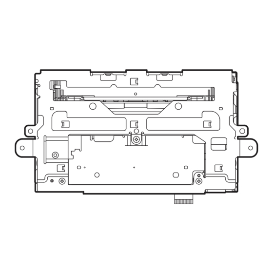
COMPONENTS
PP-2664D-A / PP-2664D-B
1.
Main unit
NOTE
*
Specifications and design are subject to change without
notice for further improvement.
*
We cannot supply PWB with component parts in prin-
ciple. When a circuit on PWB has failure, please repair
it by component parts base. Parts which are not men-
tioned in service manual are not supplied.
*
This product includes technology owned by Microsoft
Corporation and cannot be used or distributed without a
license from MSLGP.
*
In case that the main unit or the CD changer mechanism
is transported for repair, the lock pin(966-0653-00) must
be set to fix the mechanism assy.
- 1 -
Published by Service Dept.
298-6179-00 Oct.2004 P
Printed in Japan
180(W)
106.4(H)
167(D)
×
×
Approx. 3.5kg
-----------
Lock pin
PP-2664D-A
PP-2664D-B
1
Advertisement

Related Manuals for Clarion 28185 AC700


Summarization of Contents
SPECIFICATIONS
Radio Section Specifications
Tuning, reception range, sensitivity, and separation details.
CD Section Specifications
Mechanism, disc format, separation, S/N, and distortion specs.
General Unit Specifications
Load impedance, power output, voltage, and consumption.
CAUTIONS AND SAFETY PRECAUTIONS
General Safety Advice
Operating controls, servicing, and radiation exposure warnings.
Repair and Inspection Guidelines
Safety procedures for engineers during repair and inspection.
ADJUSTMENTS AND INTEGRATED CIRCUIT DETAILS
Adjustment Procedures
Details for diversity, noise, and convergence adjustments.
Integrated Circuit Pinouts and Functions
Pin descriptions for various ICs including controllers and processors.
CONNECTIONS
Connector Pin Assignments
Details for NS10, NS06, A-16, and A-12 MW connectors.
BLOCK DIAGRAM
Main Section Block Diagram
Overview of the system's architecture and signal flow.
PARTS AND EXPLODED VIEWS
Main Unit Exploded View and Parts
Visual breakdown and list of main unit components.
CD Changer Mechanism Exploded View and Parts
Visual breakdown and list of changer mechanism components.
Detailed Electrical Component Lists
Comprehensive listing of all electrical parts across PWBs.
MAIN PWB CIRCUIT DIAGRAMS
Tuner, System Control, and EQ Blocks
Schematics for tuner, system control, and EQ sections.
Power Supply and Interface Blocks
Schematics for power supply and interface sections.
PRINTED WIRING BOARDS
Main PWB-A(B1) Layouts
Component and solder side views of PWB-A.
Main PWB-B(B1) and PWB-C(B1) Layouts
Component and solder side views of PWBs B and C.
OTHER PWB LAYOUTS
CD, DSP, and Sensor PWB Layouts
Diagrams for CD, DSP, and Sensor boards.
Driver, PIM-FPC, and LED PWBs Layouts
Diagrams for Driver, PIM-FPC, and LED boards.
SPECIFIC BOARD CIRCUIT DIAGRAMS
CD PWB(B2) Circuit Diagram
Schematic for the CD PWB.
DSP PWB(B3) Circuit Diagram
Schematic for the DSP PWB.
Other PWB Circuit Diagrams
Schematics for Sensor, Driver, LED, and motor control boards.
Need help?
Do you have a question about the 28185 AC700 and is the answer not in the manual?
Questions and answers