Advertisement
Quick Links
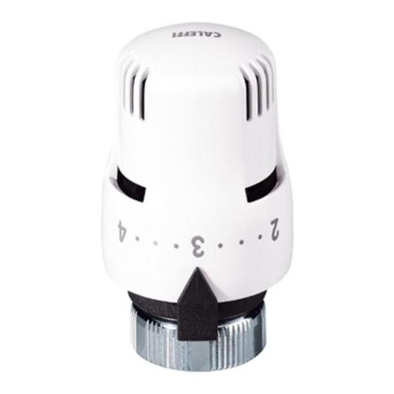
Valvole termostatiche per radiatori
Thermostatic Radiator Valve
Thermostat-Heizkörperventil
Robinetterie de radiateurs thermostatique
Thermostatische radiatorafsluiter
Comando termostático para válvulas de radiador
Válvulas termostáticas para radiador
ТЕРМОСТАТИЧЕСКИЕ ВЕНТИЛИ ДЛЯ РАДИАТОРОВ
02
Funzione - Function - Funktion - Fonctionnement -
Función - Função - Werking -
I comandi termostatici vengono utilizzati sulle valvole termostatiche o
termostatizzabili per radiatore per effettuare la regolazione automatica
della temperatura ambiente.
Thermostatic control heads are used on the thermostatic valves and
valves with thermostatic option for automatic regulation of the ambient
temperature.
Der Thermostat - Kopf Serie 200 ist einsetzbar für alle Heizkörperventile
mit Gewindeanschluss M 30 x 1,5, um die Temperatur in den jeweiligen
Räumen zu regeln.
Les têtes thermostatiques montées sur les robinets de radiateur
thermostatiques ou thermostatisables permettent la régulation
automatique de la température ambiante.
De thermostatische bedieningen worden gebruikt op thermostatische of
thermostatiseerbare radiatorventielen voor de automatische regeling
van de omgevingstemperatuur.
Os comandos termostáticos sao utilizados nas válvulas predispostas
para estes ou nas válvulas termostatizáveis para radiadores de modo a
efectuarem a regulaçao automática da temperatura ambiente.
Los mandos termostáticos se utilizan en las válvulas termostáticas
o termostatizables para radiadores para efectuar la regulación
automática de la temperatura ambiente.
Термостатические приводы используются на радиаторных термостатических
вентилях или на вентилях с термостатической опцией для осуществления
автоматической регуляции температуры в помещении.
Product Range
200000
General data
Maximum working pressure valve body:
Maximum differential pressure with control fitted:
Temperature range:
Maximum room temperature:
Scale of adjustment:
Temperature adjustment range:
Frost protection cut-in:
Length of capillary tube, series 201
Further technical details on this product are available at
200001
www.caleffi.com
www.c leffi.com
Series 200 - 201 - 209
Функция
201000
1
28001.07
I
GB
D
F
NL
P
E
RU
209000
10 bar
1 bar
5÷100°C
50°C
❄÷5
7÷28°C
~ 7°C
2 m
Advertisement

Related Manuals for CALEFFI 201 Series


Summarization of Contents
Thermostatic Radiator Valve
Product Function
Explains the use of thermostatic controls for automatic room temperature regulation.
Product Range
Displays different product codes (200000, 200001, 201000, 209000).
General Data
Details maximum pressure, temperature range, and adjustment scale.
Installation Instructions
Horizontal Installation Requirement
Thermostatic heads must be fitted in a horizontal position for correct operation.
Pre-installation Knob Setting
Set the control knob to position 5 before mounting the head onto the valve body.
Mounting on 1" Valves
Remove the adapter when mounting the control head on 1" valves.
Installation Placement Restrictions
Remote Sensor Control
Details installation requirements for the thermostatic head with a remote sensor.
Remote Sensor Installation Dimensions
Recommends following indicated dimensions for remote sensor installation.
Remote Sensor Mounting Base Installation
Temperature Setting Guide
Provides guidance on setting the thermostatic head for different room temperatures and seasons.
Tamperproof and Antitheft Features
Installing Tamperproof Shell
Details how to fit the protective shell (code 209000) for tamperproofing.
Effects of Tamperproof Shell
Shell Effect: Anti-theft Only
Applying the shell provides only an anti-theft feature without limiting temperature.
Shell Effect: Limit and Anti-theft
Applying the shell provides tamperproof limit and anti-theft features.
Shell Effect: Fixing and Anti-theft
Applying the shell provides tamperproof fixing and anti-theft features.
Temperature Limitation Procedure
Step 1: Set to Fully Open
Turn the control head to the fully open position (Pos. 5).
Step 2: Set Desired Temperature
Turn the control head to the desired maximum open position (e.g., position 3).
Temperature Fixing Procedure
Step 3: Secure Ring Nut
Secure the ring nut to lock the valve within the set temperature range.
Temperature Fixing Outcome
The valve is locked within the set temperature range.
Resetting Temperature Limits
Reset: Step 1 Release Ring Nut
Use a screwdriver to release the ring nut by pushing it towards the valve body.
Reset: Step 2 Set Desired Temperature
Position the valve at the desired temperature and turn the ring nut clockwise.
Reset Completion
Reset: Step 2 Set Open and Rotate Ring
Turn knob fully open and ring counter-clockwise; reset arrows should coincide.
Reset Outcome: No Limitation
After reset, the valve has no temperature limitation or fixing.
Need help?
Do you have a question about the 201 Series and is the answer not in the manual?
Questions and answers