Advertisement
Quick Links
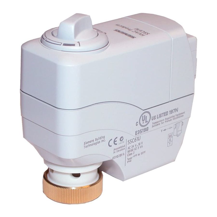
SSC Series Electronic Valve Actuator
Product Description
The SSC series actuator requires a 24 Vac, Class 2
supply and provides a 0 to 10 Vdc or Floating (three-
position) control signal. The actuator controls a
Powermite 599 Series MT Series valve with a 7/32-
inch (5.5-mm) stroke.
Warning /Caution Notations
WARNING:
CAUTION:
Product Numbers
SSC61U
0 to 10 Vdc, proportional control,
non-spring return (fail-in-place)
SSC61.5U
0 to 10 Vdc, proportional control,
spring return (fail-safe)
SSC81U
Floating control, non-spring return
(fail-in-place)
SSC81.5U
Floating control, spring return
(fail-safe)
Contents
One SSC actuator
Estimated Installation Time
20 minutes
Required Tools
•
Small Phillips head screwdriver
•
Small flat-blade screwdriver
•
Wire stripper
Item Number 129-253-07, Rev. 013
Personal injury/loss of life may
occur if you do not perform a
procedure as specified.
Equipment damage may occur
if you do not follow a
procedure as specified.
Prerequisites
WARNING:
1.
If mounting the actuator to a valve already
in line, either close the shut-off in the
piping (upstream first, then downstream)
or switch off the pump to allow the
differential pressure in the valve to drop.
2.
Disconnect the controller power before
replacing the actuator.
3.
If high voltage cable is co-located with the
SSC actuator, conduit or shielded wire
may need to be used.
CAUTION:
Before applying power, make certain a valve is
connected to the actuator.
If applying power to the actuator when a valve is
not connected, the actuator will respond to a
control signal and the shaft will extend until it
reaches its maximum end stop. Thereafter, it will
not respond to any signal.
If this occurs, disconnect the power. Turn the
manual position indicator (Figures 4 and 9) on the
top of the actuator to the 0 position and verify the
actuator shaft retracts completely.
Connect a valve to the actuator, reapply the
power, and the actuator will return to normal
operation.
Mounting
The vertical position is recommended for mounting
the actuator (Figure 1).
Figure 1.
Acceptable Actuator Mounting Positions.
Installation Instructions
Document No. 129-253
August 2, 2007
Page 1 of
4
Advertisement

Subscribe to Our Youtube Channel
Related Manuals for Siemens SSC61.5U


Summary of Contents for Siemens SSC61.5U
- Page 1 0 to 10 Vdc, proportional control, control signal and the shaft will extend until it non-spring return (fail-in-place) reaches its maximum end stop. Thereafter, it will SSC61.5U 0 to 10 Vdc, proportional control, not respond to any signal. spring return (fail-safe) If this occurs, disconnect the power.
- Page 2 Insert wiring retention screw in hole farthest from wiring terminals. (The hole nearest the wiring terminals is to secure the terminal cover in place.) Figure 4. Manual Override. Continue with Step 8. Page 2 of 4 Siemens Building Technologies, Inc.
- Page 3 Shorting Bars 120 Vac Figure 5. Manually Clearing Calibration Stroke from Figure 8. SSC81.5U Floating Control SR Neutral SSC61U and SSC61.5U Nonvolatile Memory. Switching Applications. Wiring NOTE: For proper operation, it is recommended no more than three actuators be assigned to any •...
- Page 4 Information in this publication is based on current specifications. The company reserves the right to make changes in specifications and models as design improvements are introduced. Other product or company names mentioned herein may be the trademarks of their respective owners. © 2007 Siemens Building Technologies, Inc. Siemens Building Technologies, Inc.
Need help?
Do you have a question about the SSC61.5U and is the answer not in the manual?
Questions and answers