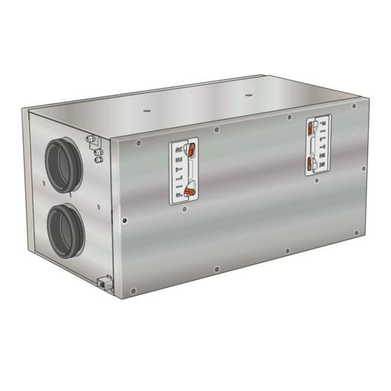
Table of Contents
Advertisement
Quick Links
Advertisement
Chapters
Table of Contents
Troubleshooting

Summarization of Contents
Important Information
Safety Information
Essential safety guidelines for installation and use of the HRV unit.
Symbols
Explanation of various symbols used throughout the manual.
Serial Number
Location of the product's serial number for servicing and support.
Recovery
Guidance on proper disposal of packaging and the unit's components.
Inspection of the Installation
Mandatory inspection procedures before commissioning the heating installation.
Delivery and Handling
Transport and Storage
Instructions for safe transport and storage of the HRV unit.
Compatible Products
Lists NIBE products compatible with the HRV unit for integrated systems.
Removing the Covers
Step-by-step guide on safely removing the unit's covers for access.
Assembly
Guidance on placing and assembling the HRV unit in its designated installation area.
Design of the HRV Unit
Pipe Connections
Identifies and explains the different pipe connection points on the HRV unit.
Sensors etc.
Lists and describes the various sensors integrated into the HRV unit.
Electrical Components
Details the electrical components and their designations within the HRV unit.
Ventilation
Explains the ventilation-related components like heat exchanger and fans.
Miscellaneous
Covers other design elements such as type plates and condensation troughs.
Ventilation Connections
Condensation Water Drain
Instructions for connecting the condensation water drain with a water seal.
General Ventilation Connections
Guidelines for installing air ducts, ensuring proper air tightness and noise reduction.
Adjusting Ventilation
Explains how to correctly position and adjust ventilation for optimal air exchange.
Ventilation Flow
Details how to connect ERS 30 for optimal airflow and pressure balance.
Electrical Connection
Overview Accessory Board (AA5)
Diagram and explanation of the accessory board for connecting external devices.
Supply
Describes how to connect the HRV unit to the power supply.
Connecting to Main Product
Details how the HRV unit connects to the main heat pump product.
Connecting to Control Module
Explains the connection of the HRV unit to the central control module.
DIP Switch
Instructions for setting DIP switches for unique unit identification.
Commissioning and Adjusting
Preparations
Checks to perform before starting up the unit, e.g., circuit breakers and filters.
Filling
Instructions on checking and filling the water seal for the condensation drain.
Start-up and Inspection
Procedures for initial start-up, inspection, and setting ventilation parameters.
Activating ERS 30
Start Guide
Describes the guided setup process upon initial heat pump installation.
Menu System
Explains how to navigate and configure settings via the unit's menu system.
Disturbances in Comfort
Troubleshooting
Guidance on identifying and resolving common operational issues and malfunctions.
Technical Data
Dimensions
Detailed physical dimensions and drawings of the HRV unit.
Technical Specifications
Lists detailed technical parameters like electrical data, ventilation, and noise levels.
Energy Labelling
Presents energy efficiency class, consumption, and heat recovery performance data.


Need help?
Do you have a question about the ERS 30-600 and is the answer not in the manual?
Questions and answers