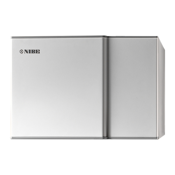
Nibe F135 User Manual
Hide thumbs
Also See for F135:
- Installation manual (40 pages) ,
- Installer manual (36 pages) ,
- User manual (24 pages)
Table of Contents
Advertisement
Quick Links
Advertisement
Table of Contents

Summary of Contents for Nibe F135
- Page 1 UHB EN 1841-2 USER MANUAL 331433 Exhaust air module NIBE F135...
-
Page 3: Table Of Contents
1 Important information Installation data Safety information Serial number Country specific information F135 – An excellent choice 2 The heating installation – the heart of the house Exhaust air module function Maintenance of F135 3 Disturbances in comfort Info-menu NIBE indoor module... -
Page 4: Important Information
Exhaust air installation (fan sp. exhaust air, normal) 5.3.14 Pump speed Serial number must always be given Certification that the installation is carried out according to instructions in the accompanying installer manual and applicable regulations. Date __________________ Signed _________________________ Chapter 1 | Important information NIBE F135... -
Page 5: Safety Information
Rights to make any design or technical modifications are reserved. ©NIBE 2018. If the supply cable is damaged, only NIBE, its service representative or similar authorised person may replace it to prevent any danger and damage. SYMBOLS NOTE This symbol indicates danger to person or machine . -
Page 6: Serial Number
Serial number The serial number can be found to the left, on top of F135. Serial number Caution You need the product's (14 digit) serial number for servicing and support. Chapter 1 | Important information NIBE F135... -
Page 7: F135 - An Excellent Choice
F135 is an accessory that makes it possible to combine an air/water heat pump with mechanical exhaust air. The heat in the building’s ventilation air is utilised by F135 and used to heat the building and the hot water at the same time as ventilating the building. F135 is connected between the indoor module and the air/water heat pump, and all control of F135 takes place from the indoor module. -
Page 8: The Heating Installation - The Heart Of The House
0 °C 22 °C -3 °C 0 °C Heat source Värmekälla The temperatures are only examples and may vary between different installations and time of year. Chapter 2 | The heating installation – the heart of the house NIBE F135... -
Page 9: Exhaust Air Module Function
The fan then routes the air to the exhaust air module heat exchanger. Here, the air releases the heating energy to the brine and the air's temperature drops significantly. The cold air is then blown out of the house. NIBE F135 Chapter 2 | The heating installation – the heart of the house... -
Page 10: Maintenance Of F135
Maintenance of F135 REGULAR CHECKS Your exhaust air module requires minimal maintenance after commis- sioning. However, it is recommended that you check your installation regularly. If anything unusual occurs, messages about the malfunction appear on the indoor module’s display in the form of various alarm texts. - Page 11 Cleaning the air filter Clean the F135's air filter regularly, how often depends on the amount of dust in the ventilation air. Select what is most suitable for your install- ation. Cut the power to the exhaust air module. Pull out the filter cassette.
-
Page 12: Disturbances In Comfort
Info-menu NIBE indoor module All the indoor module measured values are gathered under menu 3.1 in the indoor module menu system. Looking through the values in this menu can often simplify finding the source of the fault. - Page 13 In this case, the immersion heater produces heat and/or hot water. Problems withF135 do not affect heat pump operation. You do not need to select "aid mode" in event of problems with F135. Caution Selecting "aid mode” is not the same as correcting the problem that caused the alarm.
-
Page 14: Troubleshooting
BASIC ACTIONS Start by checking the following items: • That the feed cable is connected to F135. • Group and main fuses of the accommodation. • The property's earth circuit breaker. LOW OR A LACK OF VENTILATION (EXHAUST AIR INSTALLATION) •... - Page 15 – Refill the water seal with water. • Choked water seal. – Check and adjust the condensation water hose. NIBE F135 Chapter 3 | Disturbances in comfort...
-
Page 16: Technical Data
4 Technical data Detailed technical specifications for this product can be found in the in- stallation manual (nibe.eu). Chapter 4 | Technical data NIBE F135... -
Page 17: Glossary
Valve that reduces the pressure of the refrigerant, whereupon the tem- perature of the refrigerant drops. HEAT EXCHANGER Device that transfers heat energy from one medium to another without mixing mediums. Examples of different heat exchangers include evapor- ators and condensers. NIBE F135 Chapter 5 | Glossary... - Page 18 SUPPLY TEMPERATURE The temperature of the heated water that the heat pump sends out to the heating system. The colder the outdoor temperature, the higher the supply line temperature becomes. Chapter 5 | Glossary NIBE F135...
-
Page 19: Item Register
Troubleshooting, 14 Alarm, 12 Manage alarm, 12 Troubleshooting, 14 Warranty and insurance informa- tion, 6 F135 – An excellent choice, 7 Glossary, 17 Important information F135 – An excellent choice, 7 Installation data, 4 Serial number, 6 Warranty and insurance informa-... -
Page 23: Contact Information
NIBE Energy Systems OY, Juurakkotie 3, 01510 Vantaa Tel: +358 (0)9-274 6970 E-mail: info@nibe.fi www.nibe.fi NIBE Energy Systems France Sarl,Zone industrielle RD 28, Rue du Pou du Ciel, 01600 Reyrieux Tel : 04 74 00 92 92 E-mail: info@nibe.fr www.nibe.fr... - Page 24 WS version: a597 (working edition) Publish date: 2018-10-11 12:46 This manual is a publication from NIBE Energy Systems. All product illustrations, facts and data are based on the available information at the time of the publica- tion’s approval. NIBE Energy Systems makes reservations for any factual or printing errors in this manual.


Need help?
Do you have a question about the F135 and is the answer not in the manual?
Questions and answers