
Related Manuals for Absen NX3.7


Summary of Contents for Absen NX3.7
- Page 1 NX Series Product User Manual NX1.5/NX1.8/NX2.5/NX3.7 Shenzhen Absen Optoelectronic Co.,Ltd.
-
Page 2: Table Of Contents
CONTENT Safety Information ........................2 1 Product Introduction ......................5 1.1 Product application scenarios ..................7 1.2 Main features .........................7 1.3 Product parameters .....................10 2 Introduction of Product Components ................14 2.1 Product size introduction ..................... 14 2.2 Introduction of cabinet components ................17 3 Product Installation ...................... -
Page 3: Safety Information
NX Series Product User Manual SAFETY INFORMATION The following marks on the product and in this manual indicate important safety measures. WARNING: Be sure to understand and follow all safety guidelines, safety instructions, warnings and precautions listed in this manual. This product is for professional use only! This product may result in serious injury or death due to fire hazard, electric shock, and crushing hazard. - Page 4 NX Series Product User Manual If any overheating occurs, replace power cable immediately. • For any other questions, please consult a professional. Beware of Fire! • Use a circuit breaker or fuse protection to avoid fire caused by power supply cables overloading.
- Page 5 NX Series Product User Manual Standard version(Including cabinet size: 960*540mm/240*540mm): Warning: Changes or modifications to this unit not expressly approved by the party respo nsible for compliance could void the user’s authority to operate the equipment. NOTE: This equipment has been tested and found to comply with the limits for a ClassB d igital device, pursuant to part 15 of the FCC Rules.
-
Page 6: Product Introduction
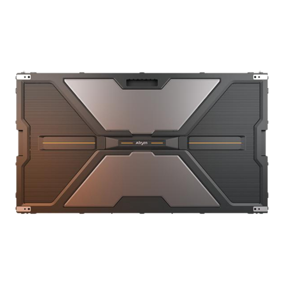
1 Product Introduction As a symbol of infinite possibilities, letter “X” becomes an exterior design element of the cabinet, and the Xs will form a “honeycomb”, an Absen brand element. The unique design conveys Absen's confidence in its display expertise and product quality. - Page 7 NX Series Product User Manual 43.5mm 960mm 540mm 45 degree cut angle on both sides of the small cabinet(Default 45° angle on both sides). 43.5mm 240mm...
-
Page 8: Product Application Scenarios
NX Series Product User Manual 1. The pixel ratio of the large cabinet (960*540mm) adopts the 16:9 mainstream video source ratio, and the picture is highly restored; 2. The small cabinet (240*540mm) adopts a quarter-size design of the large cabinet (960*540mm), which is more flexible in splicing, and better match the customer's display size requirements;... - Page 9 Adopt Absen A5C+ calibration technology, A5C+ pixel by pixel calibration technology eliminates the difference in brightness and chromaticity within and between panels, improves the uniformity of display, and reproduces...
- Page 10 NX Series Product User Manual With black screen and partial black screen dynamic energy saving function, the dynamic energy saving mode is automatically turned on during use, which is efficient and energy saving (only supported by P1.5&P1.8). The product meets the EMC Class B civil level radiation requirements (Studio version and double backup version are not included).
-
Page 11: Product Parameters
NX Series Product User Manual 1.3 Product parameters 1.3.1 800nits brightness configuration specification Cabinet size:960*540*43.5mm Parameters NX1.5 NX1.8 NX2.5 NX3.7 Diode Type SMD1212 SMD1515 SMD1515 SMD1515 Pixel Pitch (mm) 1.875 3.75 Panel Dimensions (WxHxD)/(mm) 960*540*43.5 Physical Parameter Pixel Per Panel... - Page 12 NX Series Product User Manual Cabinet size:240*540*43.5mm Parameters NX1.5 NX1.8 NX2.5 NX3.7 Diode Type SMD1212 SMD1515 SMD1515 SMD1515 Pixel Pitch (mm) 1.875 3.75 Panel Dimensions (WxHxD)/(mm) 240*540*43.5 Physical Parameter Pixel Per Panel 160*360 128*288 96*216 64*144 Panel Weight (kg)
- Page 13 NX Series Product User Manual 1.3.2 1500nits brightness configuration specification Cabinet size:960*540*43.5mm Parameters NX1.8 NX2.5 NX3.7 Diode Type SMD1515 SMD1515 SMD1515 Pixel Pitch (mm) 1.875 3.75 Panel Dimensions (WxHxD)/(mm) 960*540*43.5 Physical Parameter Pixel Per Panel 512*288 384*216 256*144 Panel Weight (kg) 10.5...
- Page 14 NX Series Product User Manual Cabinet size:240*540*43.5mm NX1.8 NX2.5 NX3.7 参数 Diode Type SMD1515 SMD1515 SMD1515 Pixel Pitch (mm) 1.875 3.75 Panel Dimensions (WxHxD)/(mm) 240*540*43.5 Physical Parameter Pixel Per Panel 128*288 96*216 64*144 Panel Weight (kg) Panel Material Die-cast aluminum...
-
Page 15: Introduction Of Product Components
NX Series Product User Manual 2 Introduction of Product Components 2.1 Product size introduction 2.1.1 Cabinet size drawing 960mm 540mm... - Page 16 NX Series Product User Manual 240mm 540mm Default 45° angle on both sides.
- Page 17 NX Series Product User Manual 2.1.2 Module size drawing 240mm 270mm...
-
Page 18: Introduction Of Cabinet Components
NX Series Product User Manual 2.2 Introduction of cabinet components 2.2.1 Cabinet size: 960*540mm Carrying handle Installation handles/ Left and right wiring holes Structural design of protective lamp Z-axis adjustment hole Rotary clamshell design Rotary clamshell design... - Page 19 NX Series Product User Manual 2.2.2 Cabinet size: 240*540mm Installation handles/ Left and right wiring holes Rotary clamshell design Default 45° angle on both sides. Small cabinets need big/small connecting block to ensure the flatness of the screen. One cabinet is equipped with two connecting blocks.
-
Page 20: Product Installation
NX Series Product User Manual 3 Product Installation This product supports full front installation and full rear installation. The upper and lower/left and right screws connecting the cabinet can be installed from the front or back of the screen, and supports wiring from the front or back of the screen. -
Page 21: Stacking Installation
NX Series Product User Manual 3.1 stacking installation 3.1.1 Installation accessories are as follows: Type Remark Schematic It is used when connecting adjacent cabinets up and down in the vertical direction (installed on the outermost side of the screen) It is used when connecting the left... - Page 22 NX Series Product User Manual 3.1.2 Installation steps: 1. Take out the NX cabinet frame from the package, first install the bottom first layer of the cabinet, install it from the middle to both sides, and then up, support the cabinet to be locked on the steel structure from the front of the cabinet or from the back of the cabinet;...
- Page 23 NX Series Product User Manual 2. Install the adjacent cabinets in sequence. Use M8*40mm bolts to fix the left and right of the cabinets, and then tighten them with an Allen wrench tool. It supports connection from the front of the cabinet or from the back of the cabinet (open the back cover of the cabinet).
- Page 24 NX Series Product User Manual 、 4. Follow the above steps to complete the installation of all cabinet structures. 5. After installing the power cable and network cable of the cabinet and checking that they are correct, install the module.
-
Page 25: Hanging Installation
NX Series Product User Manual 3.2 Hanging installation 3.2.1 Installation accessories are as follows: Specification Purpose Schematic Large cabinet (960X540mm) 960mm standard hanging beam Small cabinet (240X540mm) 240mm single hanging beam Small cabinet (240X540mm) 480mm double hanging beam The hexagon socket head... - Page 26 NX Series Product User Manual 2. Align the positioning column of the first-layer cabinet with the positioning hole of the hanging beam, and use M8*40mm screws to lock the cabinet and the hanging beam. Use M8*40mm screws to connect and lock between the left and right adjacent cabinets.
- Page 27 NX Series Product User Manual 5. Install the power cable and signal cable according to the power supply and signal routing design scheme, and then install the LED module after power-on inspection and confirmation.
-
Page 28: Wall Mounting
NX Series Product User Manual 3.3 Wall mounting 3.3.1 Unlimited splicing horizontal and vertical bar installation 3.3.1.1 Installation accessories are as follows: Type Short name Instructions for use Used when the screen is arranged in Single vertical bar 2 or 3 lines... - Page 29 NX Series Product User Manual 3.3.1.2 Installation steps: 1. Confirm the position of the wall connector: When the screen is a row of cabinets: Install the pegs on the back of the cabinet and hang them into the holes corresponding to the horizontal bar Center line of screen (composed of big cabinet, 960*540*43.5mm)
- Page 30 NX Series Product User Manual When the screen is a two-row cabinet: Center line of screen (composed of big cabinet, 960*540*43.5mm) When there are only two rows of cabinets, use one single vertical bar every three cabinets, and use one if the mantissa is less than three;...
- Page 31 NX Series Product User Manual X1 calculation method: divide the screen length of the big cabinet by 2, then subtract 480 (unit: mm); Y2 calculation method: the distance from the screen to the ground plus 480 (unit: mm); Note: The calculation units are all millimeters (mm), and the above is the...
- Page 32 NX Series Product User Manual lower left Wall connector (the lowest hole); When the screen is a cabinet with five or more rows and the number of rows is odd: Center line of screen (composed of big cabinet, 960*540*43.5mm)
- Page 33 NX Series Product User Manual As shown in the figure above, calculate the first wall connector at the lower left of the big cabinet; After installing the big cabinet, install the small cabinet; No matter whether the small cabinet is installed on the left or right, install the large cabinet first, and then install the small cabinet;...
- Page 34 NX Series Product User Manual Three T-shaped screws pass through the wall connector and are embedded in the bar, and lock the wall connector and the horizontal bar with nuts; Machine screw The connection between the horizontal bars is locked up and down by the machine screw;...
- Page 35 NX Series Product User Manual For right-angle connectors, first embed the vertical bar, then the horizontal bar, and tighten the machine screw; 3. The cabinet is fitted with pegs and hung on the horizontal bar. 4. Install the modules in sequence. Install the power cable and signal cable accableing to the power supply and signal routing design scheme, and then install the LED module after power-on inspection and confirmation.
- Page 36 NX Series Product User Manual 2. Install the NX special hanging pin in the M8 hole on the back of the cabinet, and install 4 pieces per cabinet. 3. After installing all the frames, install the cabinet frame on the frame kit, install it layer by layer from bottom to top, and fasten the connecting screws between the cabinets to fix the cabinet.
- Page 37 NX Series Product User Manual 4. After installing all the cabinets, connect the signal cable and power cable.
- Page 38 NX Series Product User Manual 5. When installing the module, it should be installed according to the corresponding number of the module and the cabinet. From the front of the big cabinet, the upper modules are XX-1, XX-2, XX-3, XX-4 from left to right, and the lower modules are XX-5, XX-6, XX-7, XX-8.
-
Page 39: Trim Pieces Installation
NX Series Product User Manual 3.4 Trim pieces installation This product supports trim pieces installation, and the trim pieces and the cabinet are locked and fixed by external hexagonal combination machine screw HM3*8. 3.4.1 The specification of the trim pieces name is as follows:... - Page 40 NX Series Product User Manual the upper side is shorter; 5. The long edge covers the short edge; The oblique side of the small cabinet is supported and fixed by the connecting block.
- Page 41 NX Series Product User Manual 3.4.3 Trim pieces Scheme diagram a. The trim pieces of the screen composed of big cabinets...
- Page 42 NX Series Product User Manual b. The trim pieces of the screen composed of small cabinets...
-
Page 43: Product Wiring
NX Series Product User Manual 4 Product Wiring 4.1 Preparation before connection Before connecting: Before supplying power to the entire screen, please carefully check whether the power cable between the cabinets is connected, and whether the main power cable between the screen and the distribution cabinet is properly connected;... -
Page 44: Signal Cable Connection
NX Series Product User Manual Cabinet-connected power cable main power cable main power cable main power cable 4.3 Signal cable connection The signal cable adopts RJ45 CAT5 network cable, and the network cable interface of the cabinet can be used for input and output. Please calculate the resolution according to the pixels of each cabinet, and connect the signal cables according to the load range of the sending card. -
Page 45: The Test Of Setting Up An Electric Circuit
NX Series Product User Manual Cabinet-connected network cable Main network cable HDMI Laptop Sending cabinet 4.4 The test of setting up an electric circuit After the cabinet connection is completed, please use a multimeter to measure whether there is short circuit at the AC input (L/N/PE) and DC output (VCC/GND) of the power supply. -
Page 46: Product Maintenance
NX Series Product User Manual 5 Product Maintenance 5.1 Preparation Tools multimeter Module front service tool Measure power cables and distribution cabinetes Installation and removal LED module Allen key Removing/installing the screws of the HUB, receiving card and power supply... -
Page 47: Module Maintenance
NX Series Product User Manual 5.2 Module maintenance (1) The module can be quickly removed with a Module front service tool. Attach the front maintenance tool to the surface of the faulty module to be taken out, press the switch for 3 to 5 seconds, and then pull the tool out to take out the module;... - Page 48 NX Series Product User Manual 5.3.2 HUB board maintenance (1) First use the pre-maintenance tool to remove the module on the cabinet; (2) Remove the 5V power cable on the hub board; (3) Then use the PH2 Phillips screwdriver to remove the screws on the fixed hub board, then it can be removed and replaced.
-
Page 49: Product Maintenance Precautions
NX Series Product User Manual 5.4 Product maintenance precautions 5.4.1 Precautions for switch on /off LED screen (1) Turn on the screen: first turn on the control computer to make it run normally, and then turn on the LED display. - Page 50 NX Series Product User Manual between the two operations; (9) Non-professionals are forbidden to touch the internal wiring of the large screen of the LED display to avoid electric shock or damage to the wiring. 5.4.3 Notes on cleaning (1) Regular cleaning and maintenance: The indoor fine pitch LED display screen will be used for a long time, and more dust will accumulate on the screen.
-
Page 51: Troubleshooting
NX Series Product User Manual inspection and repair. 5.5 Troubleshooting Common faults Solution 1. Check whether the power plug of the corresponding module is tightly inserted; 2. Check whether the power cable of the corresponding module is burnt out; 3. Check whether the switch power supply of the corresponding module has no output;... - Page 52 Make sure all wiring are normal, and only then connect power to operate the unit. All rights reserved by Shenzhen Absen Optoelectronic Co., Ltd. Shenzhen Absen Optoelectronic Co., Ltd. reserves the rights to modify contents without any further notice.
Need help?
Do you have a question about the NX3.7 and is the answer not in the manual?
Questions and answers